XC7Z010-1CLG400I Design-In Guide: Why Choose It and How to Use It
Modern embedded systems frequently present a difficult engineering trade-off: the need for sequential, control-oriented processing and the demand for high-throughput, parallel data manipulation. Traditionally, this meant a two-chip solution—a microcontroller for the software stack and an FPGA for custom hardware acceleration. This approach, however, introduces significant board space, power consumption, and inter-chip communication bottlenecks. The Xilinx (now AMD) XC7Z010-1CLG400I directly confronts this challenge by offering a tightly integrated System-on-Chip (SoC) that combines a powerful processor with flexible FPGA fabric, creating a single-chip solution for a new class of intelligent, responsive applications.

Table of Contents
The Design Challenge XC7Z010-1CLG400I Solves
The core problem for many advanced systems—from industrial motor control and machine vision to medical imaging and software-defined radio—is the concurrent need for intelligent decision-making and deterministic, low-latency processing. A standard microcontroller excels at running an operating system, managing complex communication stacks (TCP/IP, USB), and executing application logic. However, it struggles when faced with tasks requiring massive parallelism, such as processing every pixel in a video frame simultaneously or implementing a multi-channel digital filter with microsecond-level determinism. An FPGA, conversely, is built for this type of parallel work but lacks the native architecture to efficiently run a high-level OS or complex software applications.
The XC7Z010-1CLG400I, part of the Zynq-7000 family, elegantly solves this dichotomy. It is not merely an FPGA with a soft-core processor. It is a true SoC with two distinct, yet tightly coupled, sections on a single piece of silicon:
- Processing System (PS): This is a hardened, dedicated dual-core ARM Cortex-A9 MPCore processor. It functions just like a high-performance application processor, complete with its own L1/L2 cache, on-chip memory, and a rich set of standard peripherals like UART, I2C, SPI, CAN, USB, and Gigabit Ethernet. This section is responsible for running software, from bare-metal code or an RTOS (like FreeRTOS) to a full-featured operating system like Linux.
- Programmable Logic (PL): This is genuine, Artix-7 based FPGA fabric. It provides a blank slate of logic cells, block RAM, and DSP slices that can be configured to create any custom digital circuit. This is where you implement high-speed data paths, custom interfaces, real-time control loops, and algorithms that benefit from massive parallelism.
The true innovation lies in the high-bandwidth AXI4 (Advanced eXtensible Interface) interconnects that bridge the PS and PL. This is not a slow, GPIO-based bridge; it's a multi-gigabit-per-second data bus that allows the ARM cores and the FPGA fabric to share memory and stream data to each other with very low latency. This tight integration enables design patterns that are impossible with a two-chip solution. For example, the ARM processor can run a computer vision library to identify a region of interest in a video stream, then task the FPGA fabric to apply a complex, real-time filter only to that region, all while managing a web-based user interface. The XC7Z010 serves as the entry point into this powerful architecture, providing a cost-effective path for applications that need this level of integration without the resource overhead of the larger Zynq devices.
Key Specifications at a Glance
When evaluating the XC7Z010-1CLG400I for a design, these parameters, sourced from the official Zynq-7000 (DS190) datasheet, are critical for decision-making.
| Parameter | Value | Why It Matters |
|---|---|---|
| Processing System (PS) | Dual-core ARM Cortex-A9 MPCore | Provides robust, symmetric or asymmetric multiprocessing power for running an OS, managing complex software, and executing control logic. |
| Max PS Clock Frequency | 667 MHz | Determines the raw computational throughput of the processor cores. The '-1' speed grade is the slowest, offering the lowest power consumption. |
| Programmable Logic (PL) Cells | 28K | Defines the amount of configurable logic available for custom hardware. Suitable for custom peripherals, state machines, and moderate-complexity data processing pipelines. |
| Block RAM | 2.1 Mb | On-chip, high-speed dual-port memory within the PL. Essential for buffering data, implementing FIFOs, and creating local storage for hardware accelerators. |
| DSP Slices | 80 | These are dedicated 25x18 multiplier-accumulate blocks. They are crucial for accelerating digital signal processing tasks like FIR filters, FFTs, and correlations without consuming generic logic resources. |
| PS Peripherals | 2x GigE, 2x USB 2.0, 2x CAN 2.0B, 2x SD/SDIO, 2x UART, 2x I2C, 2x SPI | A rich set of hardened, standard interfaces that work out-of-the-box, freeing up PL resources for custom tasks. |
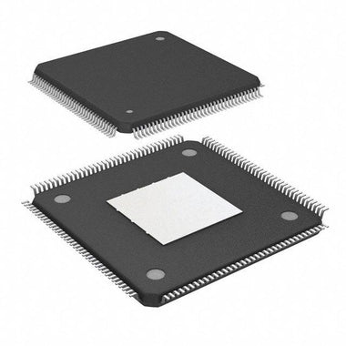
| Package | CLG400 (400-pin Chip Scale BGA) | A 17x17mm, 0.8mm pitch BGA. This high-density package dictates advanced PCB manufacturing requirements (e.g., multi-layer boards, tight routing). |
| Temperature Grade | Industrial (-40°C to 100°C Junction Temperature) | The 'I' suffix guarantees reliable operation in harsh industrial, automotive, or outdoor environments, a key requirement for non-consumer applications. |
XC7Z010-1CLG400I vs Alternatives: Head-to-Head
Choosing the right processing solution depends heavily on the specific application requirements. Here's how the XC7Z010 stacks up against other common architectural choices.
| Feature | XC7Z010-1CLG400I | High-End MCU (e.g., STM32H7) | Discrete FPGA + CPU Solution |
|---|---|---|---|
| System Integration | Excellent. CPU, FPGA, and peripherals on a single die with high-speed interconnects. | Poor. CPU with fixed peripherals only. No true programmable logic. | Poor. Requires two or more large chips, increasing board size, power, and BOM cost. |
| Real-Time Parallelism | Excellent. PL provides true, deterministic hardware parallelism for custom algorithms. | Limited. Relies on software tricks and limited DMA/peripheral capabilities. Not truly parallel. | Excellent. The FPGA provides the parallelism, but with significant latency communicating with the external CPU. |
| I/O Flexibility | Superior. PL I/O can be configured to support any digital protocol (custom or standard) at high speeds. | Fixed. Limited to the peripherals hardened on the silicon. | High. The FPGA provides flexible I/O, but inter-chip communication can be a bottleneck. |
| Development Workflow | Complex. Requires expertise in both software (Vitis for PS) and hardware (Vivado for PL) design flows. | Simple. Standard embedded C/C++ workflow using familiar IDEs. | Very Complex. Involves two separate design environments and significant board-level integration and debug effort. |
| Power Efficiency | Good. Single-chip solution is more efficient than a discrete two-chip approach. Power is highly dependent on PL usage. | Excellent. Optimized for low-power MCU applications. | Poor. Power consumption of two high-performance chips plus inter-chip I/O drivers is significant. |
When to choose the XC7Z010-1CLG400I: This SoC is the optimal choice when your application cannot be satisfied by a microcontroller alone. If you need to interface with a non-standard sensor, implement a custom high-speed communication protocol, or accelerate a specific algorithm in hardware to meet real-time deadlines, the Zynq-7010 is a strong contender. It provides a middle ground that is more powerful and flexible than any MCU, yet more integrated, power-efficient, and cost-effective than a multi-chip CPU + FPGA board. It is ideal for designers who need to partition their system into software-driven control tasks and hardware-accelerated data-path tasks, and require a high-bandwidth link between them.
Recommended Application Circuit
Designing a board around the XC7Z010-1CLG400I is a non-trivial task that requires careful attention to several key support systems. A successful design is less about a single schematic and more about correctly implementing these critical circuit blocks.
Power Delivery Network (PDN): The Zynq-7000 has a complex power architecture with multiple voltage rails for the PS core (VCCPINT), PL core (VCCINT), auxiliary logic (VCCAUX), I/O banks (VCCO), and DDR memory. A typical design requires a Power Management IC (PMIC) or several discrete switching regulators and LDOs to generate these voltages. Critically, the power-on sequence specified in the datasheet must be followed to prevent damage to the device. Each power pin on the BGA must have a set of decoupling capacitors (e.g., 10µF, 1µF, 0.1nF) placed as close as physically possible to the pin to ensure a low-impedance path to ground across all frequencies.
Boot and Configuration: The PS is the master and boots first. It then configures the PL. The boot source is selected by a set of MIO (Multiplexed I/O) pins that must be pulled high or low with resistors. The most common boot method is from an external QSPI flash memory chip. This requires connecting a 4-bit SPI flash device to the dedicated QSPI MIO pins on the Zynq. Other options include booting from an SD card, eMMC, or via JTAG for development.
DDR Memory Interface: The PS requires external DDR memory to run an OS and large applications. The XC7Z010 supports DDR3, DDR3L, DDR2, and LPDDR2. A DDR3/DDR3L interface is most common. This is a high-speed, source-synchronous interface that demands meticulous layout. The circuit must include the DDR memory chip(s), a VTT termination voltage regulator, and potentially series termination resistors on address/control lines.
Clocking and Peripherals: A single, stable clock source (typically 33.333 MHz or 50 MHz) must be provided to the PS_CLK input. From this, internal PLLs generate all necessary clocks for the PS and PL. For peripherals like Gigabit Ethernet, an external PHY chip is required, connected to the Zynq's RGMII interface. Similarly, a USB PHY is needed for the ULPI interface. A simple UART connection to a USB-UART bridge IC is essential for console access and debugging. As you select these support components, you can Browse Zynq-7000 Series related parts and reference designs to see common pairings.
PCB Layout and Thermal Design Tips
The physical design of the PCB is as critical as the electronic circuit for a Zynq-based system. The CLG400 package and high-speed interfaces present specific challenges that must be addressed.
PCB Stackup and BGA Fanout: The 0.8mm pitch of the CLG400 BGA generally requires a PCB with at least 6 to 8 layers to successfully route all signals. A "dog-bone" fanout pattern is typically used, where a via is placed next to the BGA pad and a short trace connects them. For very dense designs, more expensive via-in-pad (VIP) technology may be necessary. Careful planning of the layer stackup is crucial, ensuring uninterrupted ground planes beneath all high-speed signals.
DDR3 Interface Routing: This is the most sensitive part of the layout. Follow Xilinx's layout guidelines (e.g., from user guide UG933) religiously.
- Impedance Control: All traces must be routed with controlled impedance (e.g., 50Ω single-ended, 100Ω differential).

Alan Carter
Senior Hardware Engineer & Component Specialist
Alan has over 15 years of expertise in embedded systems design, FPGA architecture, and global semiconductor supply chains. He specializes in component cross-referencing, lifecycle management, and helping OEMs navigate supply shortages.