XC7A100T-1CSG324C Troubleshooting Guide: Common Problems and Solutions
As a senior hardware engineer, I've seen my share of board bring-up sessions go sideways. The Xilinx Artix-7 series, including the popular XC7A100T-1CSG324C, offers a fantastic balance of performance, power, and cost. However, its complexity can introduce subtle issues that are frustrating to debug. Having issues with the XC7A100T-1CSG324C? This guide covers the most common problems hardware engineers encounter during development and production, providing proven, step-by-step fixes based on official datasheet recommendations and extensive field experience.

Table of Contents
- XC7A100T-1CSG324C Quick Reference
- Problem #1: Configuration Failure (DONE Pin Stays Low)
- Problem #2: GTP Transceiver Link Instability or Failure
- Problem #3: Unstable Operation at Temperature or High Load
- Systematic Debug Checklist
- Sourcing Genuine XC7A100T-1CSG324C Components
- Frequently Asked Questions
XC7A100T-1CSG324C Quick Reference
Before diving into complex debugging, it's crucial to confirm the device's key characteristics. The XC7A100T-1CSG324C is a specific variant within the Artix-7 family with defined resources and operating conditions. Misunderstanding these can be the root of many design issues.
| Parameter | Value |
|---|---|
| FPGA Family | Artix-7 |
| Logic Cells | 101,440 |
| CLB LUTs | 63,400 |
| Total Block RAM | 4,860 Kb |
| GTP Transceivers | 8 (up to 6.6 Gb/s) |
| Maximum User I/O | 210 |
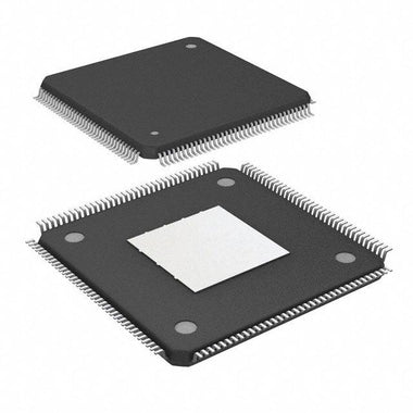
| Package | CSG324 (15x15mm) |
| Speed Grade | -1 (Slowest Commercial Grade) |
| Junction Temp. Range | 0°C to 85°C (Commercial) |
The XC7A100T is a mid-density FPGA renowned for its application in cost-sensitive, high-throughput systems. Common use cases include software-defined radio, machine vision, multi-axis motor control, and embedded processing with the MicroBlaze soft-core. Its combination of logic, Block RAM, and high-speed serial transceivers makes it a versatile choice. The -1 speed grade indicates it is the most cost-effective but also has the tightest timing margins, a critical factor in high-frequency designs. The CSG324 package is a fine-pitch BGA, which demands careful PCB layout and assembly processes.
Problem #1: Configuration Failure (DONE Pin Stays Low)
Symptom: After power-on, the FPGA fails to configure. The most obvious indicator is the DONE pin, which should be driven high by the FPGA upon successful configuration, remains low. Consequently, the device is non-operational, and JTAG may or may not be accessible.
Root Cause: This is the most common bring-up issue and almost always points to one of four areas: power supply integrity, configuration mode settings, the configuration clock, or the external configuration memory (e.g., SPI flash).
Fix: Follow this systematic approach to isolate the fault.
-
Power Supply Verification: FPGAs have strict power-on sequencing requirements. According to the Xilinx Artix-7 datasheet (DS181), the core voltage (
VCCINT) and Block RAM voltage (VCCBRAM) must ramp up before or concurrently with the auxiliary voltage (VCCAUX) and I/O voltages (VCCO).- Use a multi-channel oscilloscope to probe
VCCINT(1.0V nominal),VCCAUX(1.8V nominal), and yourVCCOrails as you power on the board. Verify they ramp monotonically and meet the sequence requirements. - Check for ripple and noise on each rail under quiescent conditions. Excessive noise, particularly on
VCCINTandVCCAUX, can prevent the configuration state machine from operating correctly. Ensure your decoupling capacitors are correctly placed and sized per the recommendations in Xilinx User Guide UG483.
- Use a multi-channel oscilloscope to probe
-
Configuration Mode Pins (M[2:0]): These pins tell the FPGA where to look for its bitstream.
- For Master SPI mode, the most common configuration, the pins should be set to
[M2, M1, M0] = [0, 0, 1]. - Physically inspect the pull-up and pull-down resistors on these pins. Measure their resistance and verify they are correctly populated. A common mistake is a misplaced resistor or a solder bridge pulling a pin to the wrong state.
- For Master SPI mode, the most common configuration, the pins should be set to
-
Configuration Clock (CCLK) and Control Signals:
- If using a Master configuration mode, the FPGA generates
CCLK. Check theConfigRatesetting in your Vivado project. If it's too high for your board layout, it can cause signal integrity issues. - Probe the
PROGRAM_Bpin. It should be high. If it's low, something is holding the FPGA in a reset state. Similarly, check theINIT_Bpin. It will go low during configuration and should go high if an error (like a CRC failure) occurs. If it's stuck low, it indicates a problem early in the boot process.
- If using a Master configuration mode, the FPGA generates
-
External Flash & Bitstream:
- Verify the SPI flash part number is on the supported list for Artix-7 devices.
- Probe the SPI interface (
CS,SCLK,MOSI) during the configuration attempt. You should see activity. If there is none, the FPGA isn't even trying to read from the flash. If there is activity but it stops, it could be a signal integrity problem or a corrupted bitstream. - Re-program the flash with a known-good, simple bitstream (like one that just blinks an LED). This helps rule out a corrupted file. Ensure the programming tool is set for the correct flash device and that the bitstream was generated for the exact XC7A100T-1CSG324C part.
Problem #2: GTP Transceiver Link Instability or Failure
Symptom: High-speed serial links using the on-chip GTP transceivers (e.g., PCIe, SGMII, Aurora) fail to establish a link, have a very high bit error rate (BER), or link up and down intermittently.
Root Cause: GTP transceivers are analog-heavy circuits that are highly sensitive to three things: the quality of the reference clock, the cleanliness of their dedicated power supplies, and the physical integrity of the high-speed differential traces on the PCB.
Fix: Debugging high-speed serial links requires precision instruments and a methodical approach.
-
Reference Clock (REFCLK) Quality:
- The GTP transceivers require a high-quality, low-jitter reference clock. The exact jitter requirements are specified in the datasheet (DS181) and depend on the protocol and line rate.
- Use a high-bandwidth oscilloscope with a jitter analysis package to measure the phase jitter of the reference clock directly at the FPGA's input pins. Compare this measurement against the datasheet requirements. Common sources of excessive jitter are noisy clock generator ICs, poor routing (stubs, crossing splits in ground planes), or incorrect termination.
-
Analog Power Supply Noise:
- The GTP transceivers have their own analog power supplies:
MGTAVCC(typically 1.0V) andMGTAVTT(typically 1.2V). These rails are extremely sensitive to noise. - Use a spectrum analyzer or the FFT function on a high-end oscilloscope to analyze the noise profile on these rails. Follow the power supply filtering and decoupling recommendations in the Artix-7 FPGAs PCB Design and Pin-Planning Guide (UG483) religiously. A single misplaced or incorrect-value capacitor can compromise link performance. Ferrite beads are often recommended to isolate these rails from noisier digital supplies.
- The GTP transceivers have their own analog power supplies:
-
Physical Channel Integrity & Vivado IBERT:
- If the clock and power are clean, the issue likely lies in the physical channel (PCB traces, connectors, cables). Impedance discontinuities are the primary culprit. While a TDR is the best tool for this, you can use Xilinx's built-in tool, the Integrated Bit Error Ratio Tester (IBERT), to diagnose the link without external equipment.
- Instantiate an IBERT core in your Vivado project. This allows you to perform various loopback tests. Start with a near-end PMA loopback. This tests the FPGA's transmitter and receiver without involving the PCB traces. If this passes, the FPGA itself is likely fine.
- Move to a far-end loopback test. This sends data out through the channel to a loopback plug or a configured partner device and back. If this fails, the problem is in the channel (your PCB traces, connectors, etc.). The eye diagram generated by IBERT will give you crucial clues about the nature of the problem (e.g., a closed eye suggests high jitter or loss, while a non-symmetrical eye might suggest impedance mismatch).
Problem #3: Unstable Operation at Temperature or High Load
Symptom: The design works perfectly for a period after power-on but then starts exhibiting random errors, logic failures, or completely freezes. The issue is more pronounced when running computationally intensive tasks or when the ambient temperature rises.
Root Cause: This classic thermal issue is caused by either the FPGA's junction temperature exceeding its maximum rating, or by timing paths that were only marginally met and fail as temperature and voltage fluctuate (PVT variation).
Fix: This problem requires a two-pronged approach: thermal analysis and static timing analysis review.
-
Thermal Management:
- The 'C' in XC7A100T-1CSG324C denotes a commercial temperature grade, with a maximum junction temperature (Tj) of 85°C. Exceeding this can cause permanent damage, but even approaching it can cause timing failures.
- Use the Vivado Power Analyzer (VPA) or the Xilinx Power Estimator (XPE) spreadsheet to get a reasonable estimate of your design's power consumption. This is not a substitute for real-world measurement but is a critical first step.
- The most direct way to monitor temperature is using the built-in System Monitor (XADC). Instantiate the XADC primitive in your design and route the temperature reading to JTAG or a UART so you can monitor it in real-time.
- If the junction temperature is approaching 85°C under load, your thermal solution is inadequate. You must add a heatsink, improve airflow with a fan, or both. Ensure the heatsink is properly attached with a quality thermal interface material (TIM).
-
Static Timing Analysis (STA):
- A design that fails at temperature often has timing paths that were barely passing at room temperature. The
-1speed grade is the slowest, making timing closure more challenging. - In Vivado, after implementation, open the timing summary report. Don't just look for a "pass/fail" result. Scrutinize the paths with the worst negative slack (WNS) for setup and worst positive slack (WHS) for hold. A path with only a few picoseconds of slack is a prime candidate for failure across PVT corners.
- Ensure your timing constraints are correct and complete. Are all clocks defined? Are input and output delays properly constrained? Use the "Report Clock Networks" and "Check Timing" tools to find unconstrained paths, which are a common source of hidden problems.
- Consider re-running implementation with different strategies or using physical optimization options in Vivado to improve timing on critical paths. Sometimes, a small change in HDL code to break up a long combinatorial path can make all the difference.
- A design that fails at temperature often has timing paths that were barely passing at room temperature. The
Systematic Debug Checklist
When a board is "dead," avoid randomly probing. Work through this checklist methodically to ensure all fundamental requirements are met before moving to more complex debugging.
| Step | Check Item | Expected Result | If Failed |
|---|---|---|---|
| 1 | Power Rails (VCCINT, VCCBRAM, VCCAUX, VCCOs) | Correct voltage, within ripple spec, correct power-on sequence. | Check VRM design, decoupling, and power-on reset circuit. |
| 2 | JTAG Chain | Vivado Hardware Manager detects the XC7A100T. | Check JTAG pod, connections, pull-up/pull-down on TCK/TMS, and VCCAUX power. |
| 3 | Configuration Mode Pins (M[2:0]) | Correct logic levels for the intended boot mode (e.g., 001 for Master SPI). | Check pull-up/down resistors and for solder shorts. |
| 4 | Control Signals (PROGRAM_B, INIT_B, DONE) | PROGRAM_B high. INIT_B goes low then high. DONE goes high after config. | Trace signals back to source. INIT_B staying low indicates a config error. DONE staying low is the primary symptom of failure. |
| 5 | Primary Clock Input | Clean, stable clock signal at the specified frequency at the FPGA pin. | Check oscillator, clock buffer, and trace integrity. |
| 6 | Configuration Flash Interface | Activity on SPI/BPI lines during boot attempt. | Check flash power, connections, and ensure the correct bitstream is loaded. |
| 7 | FPGA Temperature (via XADC) | Within operating range (e.g., < 85°C for commercial grade). | Improve thermal solution (heatsink, fan). Review design power consumption. |
This checklist forms the foundation of any FPGA board bring-up. If you can't get past step 2 (JTAG detection), the problem is very fundamental—likely a core power rail (VCCINT/VCCAUX) or a physical connection issue. If JTAG works but configuration fails, the problem lies in steps 3-6. If the device configures but is unstable, focus on steps 1 (noise under load), 5, and 7. Remember that FPGAs are complex systems on a chip; treating them as such is key to successful debugging. For more design resources and application notes, you can Browse Artix-7 Series documentation and find related components.
Sourcing Genuine XC7A100T-1CSG324C Components
In today's strained supply chain, the risk of encountering counterfeit or improperly handled components is higher than ever. For a complex and high-value device like the XC7A100T-1CSG324C, a counterfeit part is not just a waste of money—it's a source of phantom bugs and countless hours of wasted engineering time. These parts may appear physically identical but can exhibit a range of failures: non-functional JTAG, inability to configure, failing at temperature, or having drastically lower performance.
Common signs of counterfeit or substandard parts include:
- Poor Marking: Laser markings that are fuzzy, misaligned, or use the wrong font. Genuine Xilinx parts have crisp, precise markings.
- Surface Imperfections: Scratches, signs of "blacktopping" (a process of sanding and repainting a chip to hide its original identity), or inconsistent surface texture.
- Incorrect Packaging: Parts arriving in damaged or non-ESD-safe packaging, or with date codes that don't align with known production runs.
- Functional Failures: The most definitive sign is a functional failure. A part that fails basic JTAG ID code verification is almost certainly not genuine.
The only way to guarantee authenticity is to source components through a trusted and traceable supply chain. Working with an established distributor who has rigorous quality control and supplier vetting processes is paramount. This ensures that the components you receive are factory-original, have been stored in appropriate environmental conditions, and have a clear chain of custody. To secure authentic components for your production run, you can Check XC7A100T-1CSG324C Inventory & Pricing with a reliable partner.
Video Demonstration
Frequently Asked Questions (XC7A100T-1CSG324C FAQ)
Why does the DONE pin on my XC7A100T-1CSG324C stay low?
A DONE pin that remains low is the classic sign of a configuration failure. The most common causes are incorrect power supply sequencing (VCCINT must come up before or with VCCO/VCCAUX), incorrect configuration mode pin settings (M0/M1/M2), a problem with the external configuration flash memory (e.g., an incompatible chip or corrupted bitstream), or an issue with the configuration clock (CCLK). Start by verifying all power rails with an oscilloscope, then check the logic levels on the mode pins at power-up.
My JTAG chain isn't recognized by Vivado. What's wrong?
If the JTAG chain fails, Vivado cannot communicate with the FPGA. First, check the physical connections of your JTAG programmer (TDI, TDO, TCK, TMS). Second, ensure the FPGA's VCCAUX rail is powered correctly, as it powers the JTAG and configuration logic. Third, verify that the TCK and TMS pins have the appropriate pull-up or pull-down resistors as recommended in the schematic checklist. Finally, a damaged or counterfeit chip can also present with a dead JTAG interface.
My design works intermittently. How do I debug timing issues?
Intermittent failures often point to timing violations that occur under specific conditions (temperature, voltage, or data patterns). In Vivado, run a full static timing analysis (STA) and look for paths with very small timing slack (less than 100ps). These are "marginal" paths that can easily fail. Ensure all clocks are properly constrained and that you have no unconstrained paths. If the issue is temperature-related, monitor the FPGA's internal temperature with the XADC to ensure you are not exceeding the 85°C junction temperature limit for the commercial grade part.
What are the critical power supply requirements for the XC7A100T?
The XC7A100T has three critical power supply considerations. First is the power-on sequence: VCCINT (core) and VCCBRAM (Block RAM) must be stable before or at the same time as VCCAUX and VCCO rails. Second is noise: all rails, especially the analog supplies for GTP transceivers (MGTAVCC, MGTAVTT), must be very low noise, requiring careful PCB layout and decoupling. Third is voltage stability under load; your power delivery network (PDN) must be robust enough to prevent voltage droop during high-activity periods.
How can I verify my high-speed serial links are working correctly?
The best tool for verifying GTP transceiver links is the built-in Xilinx IBERT (Integrated Bit Error Ratio Tester) core. You can add this core to your design in Vivado to create eye diagrams and run BER tests without expensive external test equipment. Start with a near-end loopback test to verify the FPGA's transmitter and receiver are functional. If that passes, move to far-end tests to diagnose issues in the PCB traces, connectors, and cables.