LFE5U-25F-8BG381C Design-In Guide: Why Choose It and How to Use It
Hardware engineers frequently face the challenge of integrating high-speed interfaces like Gigabit Ethernet, PCI Express, or CPRI into systems that are constrained by cost, power, and board space. Traditional low-cost FPGAs often lack the necessary high-speed SERDES transceivers, forcing a jump to much larger, more power-hungry, and expensive devices. This creates a design gap where the solution is either under-featured or over-engineered. The Lattice LFE5U-25F-8BG381C is specifically engineered to fill this gap, offering a balanced blend of logic, DSP resources, and high-speed SERDES in a compact, low-power, and cost-effective package.

Table of Contents
The Design Challenge LFE5U-25F-8BG381C Solves
The core challenge for many modern electronic systems is high-speed data aggregation and interface bridging. Consider designing a compact industrial camera, a small cell radio head, or a multi-channel video converter. These applications require a central processing unit to manage multiple data streams, perform real-time processing, and communicate with the outside world over standard high-speed links. The LFE5U-25F-8BG381C, part of Lattice's ECP5 family, is purpose-built for this "edge connectivity" role.
Here's a breakdown of the specific problems it addresses:
- The SERDES Gap: Many designs need just one or two high-speed serial links—perhaps for a Gigabit Ethernet PHY, a PCIe Gen 1 endpoint, or interfacing with a high-resolution image sensor. Using a high-end FPGA with 16 or 32 SERDES channels is wasteful in terms of cost, power, and PCB footprint. The LFE5U-25F-8BG381C provides four 3.2 Gbps SERDES channels, hitting the sweet spot for a wide range of connectivity tasks without the overhead of its larger counterparts.
- Low-Power Signal Processing: While the SERDES brings data into the chip, that data often needs pre-processing. This could be filtering, color space conversion, or FFTs. The ECP5 architecture integrates 52 sysDSP slices, which are hardened 18x18 multipliers with accumulators. Offloading these math-intensive operations from the general-purpose fabric to dedicated DSP blocks significantly reduces power consumption and frees up LUTs for control logic. This allows for powerful signal processing within a tight thermal budget.
- Cost-Effective Interface Bridging: This FPGA excels at protocol conversion. It can take in data from a parallel CMOS sensor, buffer it in its 1008 kbits of embedded block RAM (EBR), and then serialize it for output over a DisplayPort or Ethernet link. Its flexible I/O supports a wide range of signaling standards (LVDS, LVCMOS, etc.), making it an effective "Swiss Army knife" for connecting disparate components on a PCB. This eliminates the need for multiple, single-function ASSP bridge chips, simplifying the BOM and reducing board complexity.
In essence, the LFE5U-25F-8BG381C provides a path for designers to add high-value connectivity and processing features to their products without incurring the cost, power, and design complexity penalties typically associated with SERDES-capable FPGAs. It is the ideal choice when an application has outgrown the capabilities of a simple CPLD or non-SERDES FPGA but does not warrant the full power of a top-tier device.
Key Specifications at a Glance
Understanding the core specifications of the LFE5U-25F-8BG381C is crucial for determining its suitability for your design. The following table highlights the parameters most relevant to a design-in decision, based on the official Lattice ECP5 family datasheet.
| Parameter | Value | Why It Matters |
|---|---|---|
| Logic Elements (LUTs) | 24K | This is the fundamental measure of logic capacity. 24K LUTs are sufficient for complex state machines, control logic, and gluing together various IP blocks for applications like video processing or industrial control. |
| SERDES Channels | 4 channels, up to 3.2 Gbps | This is the key feature. These channels can implement standard protocols like PCI Express Gen 1, Gigabit Ethernet (SGMII), CPRI, and JESD204B, enabling high-speed connectivity in a small form factor. |
| DSP Slices (sysDSP) | 52 (18x18 multipliers) | Essential for any signal processing task. These dedicated hardware blocks efficiently perform multiplication and accumulation for filters (FIR, IIR), FFTs, and other algorithms, saving power and logic resources. |
| Embedded Block RAM (EBR) | 1008 kbits | Provides on-chip memory for data buffering, which is critical for bridging interfaces with different data rates, implementing frame buffers in video applications, or storing coefficients for DSP algorithms. |
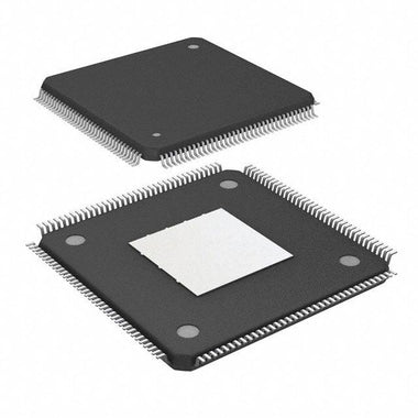
| Package | 381-ball caBGA (19x19, 1.0mm pitch) | The 1.0mm pitch is relatively easy to manufacture on standard multi-layer PCBs, avoiding the need for more expensive HDI or via-in-pad technology required by finer-pitch packages. |
| Speed Grade | -8 | This is the fastest commercial speed grade for the ECP5 family, ensuring that timing closure can be met for high-performance designs. |
| Maximum User I/O | 205 | Provides ample general-purpose I/O for connecting to slower peripherals, memory, microcontrollers, and other system components, in addition to the high-speed SERDES interfaces. |
| Temperature Grade | Commercial (0°C to 85°C Junction) | Suitable for a wide range of indoor and controlled-environment applications. For more demanding environments, industrial-grade (-I) versions are available in the ECP5 family. |
LFE5U-25F-8BG381C vs Alternatives: Head-to-Head
When selecting a mid-range FPGA, the LFE5U-25F-8BG381C often competes with offerings from Xilinx and Intel (formerly Altera). Here's how it stacks up against comparable devices.
| Feature | Lattice LFE5U-25F-8BG381C | Xilinx Artix-7 (XC7A35T) | Intel Cyclone V E (5CEFA2) |
|---|---|---|---|
| Logic Density | 24K LUTs | ~20K LUTs (33K Logic Cells) | 25K Logic Elements (~9.5K LUTs) |
| SERDES | 4x 3.2 Gbps | 4x 6.6 Gbps (GTP Transceivers) | 3x 3.75 Gbps |
| DSP Blocks | 52 (18x18) | 90 (18x25) | 66 (18x18) |
| Power Consumption | Low (Optimized for low static/dynamic power) | Low to Medium (Higher performance SERDES can increase power) | Low (Designed for low power applications) |
| Core Architecture | FPGA fabric with soft IP | FPGA fabric with soft IP | FPGA fabric; some variants include a hard processor system (ARM Cortex-A9) |
| Design Tools | Lattice Diamond (Free license available) | Xilinx Vivado (Free WebPACK edition available) | Intel Quartus Prime (Free Lite edition available) |
The decision of when to choose the LFE5U-25F-8BG381C comes down to a careful balance of performance, power, and cost. If your design requires the absolute highest SERDES data rates (e.g., PCIe Gen 2 or 10GbE), an Artix-7 or higher-end device is the necessary choice. However, the Artix-7's more capable SERDES comes at a potential cost in power consumption and unit price.
The Intel Cyclone V E is a strong competitor, but its logic element architecture differs, making direct LUT comparisons tricky. The key differentiator for some Cyclone V parts is the optional Hard Processor System (HPS), which is a major advantage if you need a full-fledged ARM processor. If you only need a soft-core processor or no processor at all, this feature is unnecessary overhead.
The LFE5U-25F-8BG381C shines in the vast middle ground. It is the optimal choice for applications where 3.2 Gbps SERDES is "good enough" for the required interface (like GigE, DisplayPort, or PCIe Gen 1) and the primary design drivers are low power consumption, a small footprint, and a BOM cost that is significantly lower than higher-performance FPGAs. Its architecture is streamlined for connectivity and co-processing, making it a highly efficient solution for its target applications.
Recommended Application Circuit
Successfully integrating the LFE5U-25F-8BG381C into your design requires careful attention to its power delivery network (PDN), configuration circuitry, and high-speed interfaces. While you should always consult the official Lattice ECP5 Hardware Checklist and schematic design guides, here are the key areas to focus on.
Power Supply Design: The ECP5 requires several power rails, each with specific requirements:
- VCC (1.1V): This is the core voltage for the FPGA fabric. It draws the most current and is highly dynamic. A dedicated switching regulator is recommended, followed by extensive bulk and high-frequency decoupling capacitors placed as close to the BGA balls as possible.
- VCCAUX (2.5V or 3.3V): This rail powers auxiliary internal logic, including the PLLs and parts of the I/O structure. It requires clean power, so proper filtering is essential.
- VCCIO (1.2V to 3.3V): There are multiple VCCIO banks, each powering a set of I/O pins. This allows you to interface with devices using different logic levels (e.g., a 1.8V sensor and 3.3V microcontroller) without external level shifters. Each VCCIO rail must be decoupled independently.
- VCCJ (1.2V, 1.35V, 1.5V, 1.8V): This is the dedicated supply for the JTAG interface.
Power supply sequencing is critical. The Lattice documentation specifies the recommended power-up and power-down sequence for these rails to prevent damage to the device. Typically, VCC, VCCAUX, and then VCCIO is a safe sequence.
Configuration and JTAG: The LFE5U-25F-8BG381C is SRAM-based and must be configured at every power-up. The most common method is Master SPI mode, where the FPGA reads its configuration bitstream from an external SPI flash memory. The circuit requires a 4-wire SPI connection between the FPGA and the flash chip, along with pull-up/pull-down resistors on key configuration pins (PROGRAMN, DONE, INITN) as specified in the datasheet. The JTAG interface (TDI, TDO, TCK, TMS) should always be brought out to a header for debugging and in-system programming during development.
When selecting supporting components, you can Browse ECP5 Series related application notes on our site or refer to Lattice's reference designs for suitable SPI flash and power management ICs.
PCB Layout and Thermal Design Tips
A successful LFE5U-25F-8BG381C design hinges on a robust PCB layout. The 381-ball BGA package requires a multi-layer board, typically 6 to 8 layers for proper signal and power routing.
BGA Fanout: The 1.0mm ball pitch of the BG381 package is manageable with standard PCB fabrication processes. A "dog-bone" fanout, where traces exit the BGA pads to a via placed just outside the pad, is the most common and cost-effective method. This typically allows for one trace between adjacent vias. For more dense routing, via-in-pad (VIP) technology can be used, but this significantly increases PCB cost.
Power Delivery Network (PDN): Use solid ground and VCC planes directly beneath the FPGA. This creates a low-inductance path for power and provides a reference for controlled-impedance signals. Place decoupling capacitors on the bottom side of the PCB directly under the FPGA, with vias connecting them as close as possible to the corresponding VCC and GND balls. Use a mix of capacitor values (e.g., 10uF, 1uF, 0.1uF, 0.01uF) to provide low impedance across a wide frequency range.
SERDES Routing: This is the most critical part of the layout. SERDES signals must be routed as 100-ohm differential pairs. Maintain tight coupling between the P and N traces, keep them on the same layer as much as possible, and minimize the use of vias. Any vias used must have adjacent ground vias to provide a continuous return path. Ensure the trace lengths of the pair are matched to within a few mils to prevent skew. Route these signals away from noisy sources like clock lines or switching power supplies.
Thermal Management: Although the ECP5 is a low-power family, a design that heavily utilizes the DSP and SERDES blocks can generate significant heat. The primary path for heat to escape the package is through the BGA balls into the PCB. A grid of thermal vias placed in the ground plane directly under the chip will help conduct heat away from the package and into the inner/outer ground planes, which act as a heatsink. Ensure a solid copper connection from the BGA ground balls to this thermal via array.
Where to Buy LFE5U-25F-8BG381C
The LFE5U-25F-8BG381C is a well-established and popular member of the Lattice ECP5 family, making it widely available through authorized distributors. As a high-volume component, it is typically supplied in JEDEC trays for automated pick-and-place assembly lines. For prototyping and small-batch runs, some distributors may offer cut-tape or individual unit quantities.
When planning for production, it's essential to consider lead times. While this part is generally well-stocked, global supply chain dynamics can affect availability. We recommend engaging with your distribution partner early in the design cycle to secure supply for your production timeline. The part number LFE5U-25F-8BG381C specifies the device type (LFE5U-25F), speed grade (-8), package (BG381), and temperature range (C - Commercial). Be sure to use the exact part number when ordering to avoid receiving a different variant.
For the most up-to-date availability and competitive quotes for your project, you can Check LFE5U-25F-8BG381C Inventory & Pricing on our global component search engine.
Video Demonstration
Frequently Asked Questions (LFE5U-25F-8BG381C FAQ)
What is the main advantage of the LFE5U-25F-8BG381C over a similarly sized Xilinx Artix-7?
The primary advantage is the balance of cost and power for a specific performance tier. While an Artix-7 device may offer higher SERDES speeds (e.g., 6.6 Gbps vs 3.2 Gbps), the LFE5U-25F-8BG381C is optimized for applications where 3.2 Gbps is sufficient, such as Gigabit Ethernet or PCIe Gen 1. This optimization results in lower static and dynamic power consumption and typically a lower unit cost, making it a more efficient choice for power-sensitive and cost-constrained designs.
What configuration modes does the LFE5U-25F-8BG381C support?
The LFE5U-25F-8BG381C supports a variety of configuration modes to load its bitstream. The most common is Master SPI, where the FPGA acts as the master and reads its configuration from an external SPI flash chip. Other supported modes include Slave SPI, Master/Slave Parallel (SSPI/MSPI), and direct programming via the JTAG interface, which is primarily used for development and debugging.
What are the core voltage requirements for this FPGA?
The LFE5U-25F-8BG381C requires several distinct power rails for proper operation. The core logic fabric runs on a 1.1V supply (VCC). The auxiliary internal logic and PLLs require a 2.5V or 3.3V supply (VCCAUX). Finally, the I/O banks are powered by VCCIO rails, which can be set independently from 1.2V to 3.3V to match the logic levels of connected devices.
Can the SERDES on the LFE5U-25F-8BG381C be used for PCI Express?
Yes, the SERDES channels are capable of implementing a PCI Express (PCIe) interface. They fully support the PCIe Gen 1.1 specification, which runs at 2.5 GT/s. You can implement up to a x4 PCIe Gen 1 endpoint using the four available SERDES channels, making this FPGA an excellent choice for creating custom PCIe peripheral cards or adding PCIe connectivity to an embedded system.
What software is used to program the LFE5U-25F-8BG381C?
The complete design flow for the LFE5U-25F-8BG381C is managed using Lattice Diamond software. This integrated design environment includes tools for HDL synthesis, place and route, static timing analysis, power calculation, and bitstream generation. Lattice Diamond has a free license option that provides full support for the ECP5 family, making it accessible for projects of any scale.