LFE5U-25F-8BG381C Design-In Guide: Why Choose It and How to Use It
Hardware engineers frequently face the challenge of integrating high-bandwidth data streams from sensors, displays, and networks into a single, power-efficient system. Microcontrollers often lack the necessary parallel processing power and high-speed I/O, while larger FPGAs can introduce unacceptable cost, power, and complexity. This creates a design gap for applications requiring a blend of high-speed connectivity, real-time processing, and cost-effectiveness. The Lattice LFE5U-25F-8BG381C, part of the ECP5 family, is engineered specifically to fill this gap, offering a compelling mix of features for bridging, aggregation, and co-processing in a compact form factor.

Table of Contents
The Design Challenge LFE5U-25F-8BG381C Solves
In modern embedded systems, from industrial automation to machine vision and communication hubs, the demand for processing more data faster is relentless. A common engineering problem is interfacing multiple high-speed peripherals—like MIPI CSI-2 image sensors, Gigabit Ethernet PHYs, or PCIe endpoints—to a central processor that may have limited I/O capabilities. For example, a cost-optimized application processor might only have a single camera interface, but the product requires two. Or, a system might need to aggregate data from several low-speed serial streams into a single high-speed uplink. Using a general-purpose processor for these real-time, high-bandwidth tasks can lead to software bottlenecks and unpredictable latency.
This is precisely where the LFE5U-25F-8BG381C excels. It is not designed to be the most powerful FPGA on the market, but rather the most efficient solution for a specific class of problems. It acts as a highly flexible "smart bridge" or "co-processor." Its architecture is optimized for low-power, high-bandwidth connectivity. With its built-in SERDES (Serializer/Deserializer) channels, it can natively handle protocols like PCI Express Gen 1, Gigabit Ethernet (SGMII), and CPRI without requiring expensive external components. This makes it an ideal choice for:
- Video Bridging: Aggregating multiple MIPI or LVDS video streams into one, or converting between interface standards (e.g., LVDS to MIPI DSI).
- Industrial Control: Implementing multiple motor control loops, processing sensor data in parallel, and driving custom industrial communication protocols with deterministic timing that a software-based approach cannot guarantee.
- Communication Gateways: Creating a small-footprint device that can bridge different network types, such as connecting a fiber optic SFP module (via SGMII) to an internal system bus.
- CPU Offload: Handling computationally intensive tasks like FIR filtering, FFTs, or image pre-processing using its dedicated DSP slices, freeing up the main CPU for application-level logic.
By providing a balanced combination of 24K LUTs for custom logic, dedicated DSP blocks for math-intensive operations, and versatile SERDES for high-speed I/O, the LFE5U-25F-8BG381C allows engineers to solve complex interface and processing challenges in a single, cost-effective, and low-power component. It avoids the overkill of mid-range FPGAs while providing a significant leap in capability over traditional microcontrollers.
Key Specifications at a Glance
The decision to select an FPGA often comes down to a few critical parameters. The following table highlights the specifications for the LFE5U-25F-8BG381C, sourced directly from the official Lattice ECP5 family datasheet.
| Parameter | Value | Why It Matters |
|---|---|---|
| Logic Elements (LUTs) | 24K | Defines the core capacity for implementing custom logic, state machines, and control structures. 24K is a sweet spot for many bridging and co-processing tasks. |
| DSP Slices | 52 | These are hardened 18x18 multipliers, essential for signal processing, filtering, and arithmetic-heavy algorithms. Using DSP slices is far more efficient than implementing multipliers in general-purpose logic. |
| Embedded Block RAM (EBR) | 1008 kbits | Provides on-chip memory for data buffering, implementing FIFOs, and storing coefficients. Crucial for handling bursts of data in video and communication applications. |
| SERDES Channels | 4 | The key enabler for high-speed interfaces. Each channel can support multi-gigabit rates for protocols like PCIe, SGMII (Gigabit Ethernet), XAUI, and CPRI. |
| Maximum User I/O | 259 | A high I/O count in a compact package allows for interfacing with numerous peripherals and system components simultaneously. |
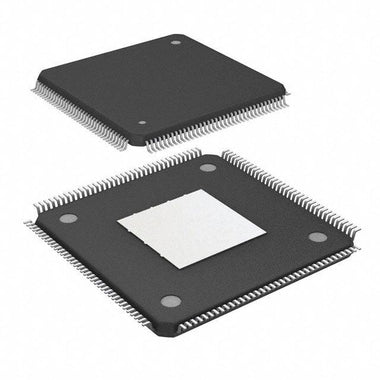
| Package | 381-ball caBGA (17x17 mm) | The ball-grid array package provides high I/O density. The 17x17 mm footprint is suitable for space-constrained designs. |
| Speed Grade | -8 | This is the fastest commercial speed grade for the ECP5 family, enabling higher clock frequencies and meeting tighter timing constraints for demanding applications. |
| Core Voltage (VCC) | 1.1 V | The low core voltage is a key contributor to the ECP5's low static and dynamic power consumption, making it suitable for thermally sensitive or battery-powered devices. |
LFE5U-25F-8BG381C vs Alternatives: Head-to-Head
When selecting a small-form-factor FPGA, the LFE5U-25F-8BG381C often competes with offerings from Xilinx (now AMD) and Intel (formerly Altera). Here's an honest comparison against similarly positioned devices.
| Feature | Lattice LFE5U-25F-8BG381C | Xilinx Artix-7 (e.g., XC7A35T) | Intel Cyclone V E (e.g., 5CEFA2) |
|---|---|---|---|
| Core Focus | Low-power, cost-effective connectivity with SERDES. | Higher logic density and performance per watt. | Flexible logic fabric, with SoC options available in the family. |
| SERDES | 4 channels, optimized for common protocols like SGMII and PCIe Gen 1/2. | 4 transceivers, generally more feature-rich and capable of higher speeds. | 4 transceivers, highly configurable for various standards. |
| DSP Blocks | 52 (18x18) slices. Good for basic to moderate signal processing. | 90 (18x25) DSP48E1 slices. More powerful and numerous. | 30 (18x18) multipliers. Fewer than the others in this class. |
| Power Consumption | Generally lower static power consumption, a key advantage in standby modes. | Competitive dynamic power, but static power can be higher. | Good overall power efficiency, but can be higher than ECP5 in some scenarios. |
| Development Tools | Lattice Diamond. Often seen as simpler and faster to compile for smaller designs. | AMD Vivado. A very powerful but complex tool suite with a steeper learning curve. | Intel Quartus Prime. A mature and robust toolchain, well-regarded by many engineers. |
| Cost Position | Often the most cost-effective option for designs requiring SERDES functionality. | Can be more expensive, but offers more logic and DSP resources for the price. | Competitively priced, especially when considering the feature set. |
The decision of when to choose the LFE5U-25F-8BG381C comes down to design priorities. If your primary challenge is bridging interfaces using one or two SERDES channels (like dual Gigabit Ethernet) and performing moderate signal processing on a tight power and cost budget, the ECP5 is an extremely strong contender. Its lower static power is a significant benefit for devices that are always on but not always active. The simplicity of the Lattice Diamond toolchain can also accelerate development time for teams focused on connectivity rather than complex algorithmic implementation. In contrast, if your design is dominated by complex algorithms requiring a large number of DSP slices and maximum logic density, an Artix-7 might be a better fit despite its potentially higher cost and power draw. If you anticipate needing a hard processor core in the future or are already invested in the Intel ecosystem, a Cyclone V E would be the logical path.
Recommended Application Circuit
A successful design with the LFE5U-25F-8BG381C hinges on a robust support circuit, particularly for power and configuration. A typical implementation involves several key areas.
Power Delivery Network (PDN): The ECP5 requires a few key voltage rails. The core logic runs on VCC (1.1V). The auxiliary logic and PLLs use VCCAUX (2.5V or 3.3V). Each of the I/O banks has its own VCCIO supply, which can be set independently (e.g., 1.8V, 2.5V, 3.3V) to match the logic levels of connected devices. It is critical to follow the datasheet's power-on sequencing recommendations to avoid damaging the device. A Power Management IC (PMIC) or discrete regulators with enable pins can be used to control the sequence. Each power pin on the BGA must have a dedicated decoupling capacitor (typically 100nF) placed as close as possible, with bulk capacitance (10-47uF) for each rail located nearby.
Configuration and JTAG: The most common configuration method is Master SPI mode. In this setup, the FPGA acts as the SPI master and reads its configuration bitstream from an external SPI flash memory upon power-up. The circuit requires connecting the FPGA's SPI pins (CS, MISO, MOSI, SCLK) to a standard SPI flash device. The PROGRAMN pin should be pulled high via a resistor and can be driven low to initiate a reconfiguration. The DONE pin, which signals successful configuration, should have a pull-up resistor. For development and debugging, the standard JTAG port (TMS, TCK, TDI, TDO) must be brought out to a header compatible with a Lattice programming cable.
High-Speed Interfaces: The SERDES channels require precise layout. Each differential pair (TXP/TXN, RXP/RXN) must be routed with 100-ohm differential impedance. AC coupling capacitors (typically 100nF) are required on the transmit or receive lines for most protocols like SGMII and PCIe. Consult the specific protocol documentation and Lattice application notes for exact placement and value recommendations. The entire Browse ECP5 Series is designed to make these high-speed interfaces accessible and cost-effective.
PCB Layout and Thermal Design Tips
Proper PCB layout is not optional for an FPGA like the LFE5U-25F-8BG381C; it is essential for functionality, signal integrity, and thermal stability.
BGA Fanout and Decoupling: The 381-ball caBGA package requires careful fanout. A "dog-bone" fanout, where a via is placed adjacent to the BGA pad, is the standard approach. Place decoupling capacitors on the bottom side of the board directly under the BGA pins they are servicing to minimize inductance. Use multiple vias for each power and ground ball to create a low-impedance path to the internal planes. A solid, uninterrupted ground plane directly beneath the FPGA is critical for signal integrity and provides a return path for high-speed signals.
Signal Integrity: For high-speed differential pairs like the SERDES channels, maintain tight intra-pair length matching (typically within 5 mils) and route them on a single layer with a solid reference plane. Avoid routing them over plane splits or near noisy signals like switching power supplies. For single-ended interfaces like a DDR3 memory bus, ensure that clock, address, and data lines are length-matched according to the memory controller's requirements.
Thermal Management: The LFE5U-25F-8BG381C is a low-power device, but high-utilization designs can still generate significant heat. The primary path for heat to escape is through the BGA balls into the PCB. To aid this, create a grid of thermal vias in the center of the BGA footprint, connecting the top-side pads directly to the internal ground planes. These planes act as a large heat spreader. For a design running the SERDES channels at high speed and utilizing a majority of the DSP and logic resources, a thermal simulation is highly recommended. If the junction temperature is projected to exceed the datasheet limits (the 'C' in the part number denotes a commercial temperature range), a small, low-profile heatsink may be required.
Where to Buy LFE5U-25F-8BG381C
The LFE5U-25F-8BG381C is a widely used component within the Lattice ECP5 family, valued for its balance of features and cost. It is typically available from authorized distributors and component suppliers. The part is supplied in a 17x17mm, 381-ball caBGA package. When planning your production, it's important to consider that lead times for FPGAs can fluctuate based on global supply and demand. Engaging with your supplier early in the design cycle is a prudent strategy to secure inventory and manage your bill of materials timeline effectively.
For procurement professionals and engineers looking to source this part, it is crucial to work with a reliable distributor to ensure authenticity and avoid counterfeit components. You can Check LFE5U-25F-8BG381C Inventory & Pricing to get up-to-date information on availability and to place an order for your project or production run.
Video Demonstration
Frequently Asked Questions (LFE5U-25F-8BG381C FAQ)
What are the main advantages of the LFE5U-25F-8BG381C over a Xilinx Artix-7 or Intel Cyclone V?
The primary advantages of the LFE5U-25F-8BG381C are its optimized balance of cost, power, and high-speed connectivity. It often presents a lower unit cost for designs requiring SERDES functionality compared to its competitors. Furthermore, the ECP5 family is known for its low static power consumption, which is a critical advantage in battery-powered or thermally constrained applications where the device may be in an idle state for long periods. While an Artix-7 may offer more raw logic and DSP performance, and a Cyclone V may offer SoC variants, the ECP5 excels in the specific niche of a cost-effective, low-power "smart bridge" FPGA.
What is the "-8" speed grade, and when do I need it?
The "-8" in LFE5U-25F-8BG381C denotes the fastest speed grade available for the commercial temperature range of this device. A faster speed grade means the internal logic paths and I/O structures have lower propagation delays. You should select the -8 speed grade for designs that have tight timing requirements, operate at high clock frequencies, or push the performance limits of the SERDES or memory interfaces. If your design is simpler, with lower clock rates, you might be able to use a slower (and potentially lower cost) speed grade like -6 or -7, but the -8 grade provides the most timing margin.
How do I configure or program the LFE5U-25F-8BG381C?
The most common method is using Master SPI mode. In this configuration, the FPGA automatically reads its bitstream from an external SPI flash chip upon power-up. You only need to connect the FPGA's dedicated configuration SPI pins to the flash. For development, debugging, and initial programming of the SPI flash, you use the JTAG interface. This requires connecting the TDI, TDO, TCK, and TMS pins to a JTAG header, which you can then connect to a Lattice USB programming cable and control via the Lattice Diamond software.
What are the critical power supply rails for this FPGA?
There are three main types of power rails you must provide. The first is the core voltage, VCC, which is 1.1V and powers the internal logic fabric. The second is the auxiliary voltage, VCCAUX, which powers PLLs and some I/O logic and is typically 2.5V or 3.3V. Finally, each I/O bank has its own VCCIO supply, which can be set independently to levels like 1.8V, 2.5V, or 3.3V to match the voltage of the devices you are interfacing with. It's critical to provide clean, well-decoupled power for all these rails and to follow the power-on sequencing specified in the datasheet to ensure reliable operation.
Can the LFE5U-25F-8BG381C handle a Gigabit Ethernet interface?
Yes, absolutely. This is one of its key applications. The LFE5U-25F-8BG381C has four SERDES channels that can be configured to implement the SGMII protocol, which is the standard interface between a MAC and a Gigabit Ethernet PHY. You can implement an Ethernet MAC within the FPGA fabric and connect it via SGMII to an external PHY chip. Alternatively, for direct fiber optic connections, you can connect the SERDES channels directly to an SFP transceiver module, implementing both the MAC and the PCS/PMA layers within the FPGA.