10M16SAU169I7G Intel (Altera) MAX 10 FPGA: Datasheet, Pinout, Specifications & Application Guide
The 10M16SAU169I7G is a non-volatile FPGA from the Intel (formerly Altera) MAX 10 family, built on a 55 nm flash process. Featuring 16,000 logic elements, an integrated ADC, and internal configuration storage in a compact UBGA-169 package, this industrial-grade device is designed for cost-sensitive embedded systems that demand instant-on capability and single-chip integration. In this guide we walk through its core specifications, block diagram, pinout, typical application circuits, and design best practices.
Table of Contents
- 1. Overview & Key Features
- 2. Technical Specifications
- 3. Block Diagram
- 4. Pinout & Package Information
- 5. Application Circuit & Design Guide
- 6. Frequently Asked Questions
1. Overview & Key Features
The MAX 10 FPGA family delivers a unique combination of non-volatile flash-based configuration, analog-to-digital conversion, and programmable logic in a single device. The 10M16SAU169I7G variant targets industrial applications with an extended temperature range of −40 °C to +100 °C and speed grade 7.
Key advantages of the 10M16SAU169I7G include:
- Instant-on – Internal flash stores the configuration bitstream, eliminating the need for an external configuration device and enabling power-on in less than 10 ms.
- Integrated ADC – A built-in 12-bit successive-approximation-register (SAR) ADC with up to 18 analog input channels simplifies mixed-signal designs.
- Dual configuration images – User flash memory supports dual-boot and remote update for field upgrades.
- Compact footprint – The 11×11 mm UBGA-169 package suits space-constrained PCB layouts.
- Low power – 1.2 V core voltage and advanced power management features reduce total system power.
For engineers sourcing programmable logic devices, the MAX 10 family competes with Lattice MachXO3 and Microchip PolarFire families, while the Intel FPGA catalog at wwdparts offers the full range of MAX 10 ordering options.
2. Technical Specifications
| Parameter | Value |
|---|---|
| Part Number | 10M16SAU169I7G |
| Family | Intel (Altera) MAX 10 |
| Logic Elements (LEs) | 16,000 |
| Logic Array Blocks (LABs) | 1,000 |
| Embedded Memory (M9K) | 549 Kb (562,176 bits) |
| User Flash Memory (UFM) | Internal – dual configuration images |
| 18 × 18 Multipliers | 45 |
| PLLs | 4 |
| Max User I/O (U169) | 130 |
| ADC | 12-bit SAR, up to 1 MSPS |
| External Memory Interfaces | DDR3, DDR2, LPDDR2, SRAM |
| I/O Standards | 3.3V / 2.5V / 1.8V / 1.5V LVCMOS & LVTTL; LVDS, RSDS, mini-LVDS |
| Core Voltage | 1.2 V |
| I/O Voltage | 1.0 V – 3.3 V |
| Package | UBGA-169 (11 × 11 mm, 0.8 mm pitch) |
| Temperature Range | −40 °C to +100 °C (Industrial) |
| Speed Grade | 7 |
| Process Technology | 55 nm flash |
| Configuration | Internal (no external ROM needed) |
| RoHS / Lead-Free | Yes (Green / “G” suffix) |
3. Block Diagram
The functional block diagram below illustrates the internal architecture of the MAX 10 FPGA, including the logic array, embedded memory blocks, PLL clock network, ADC subsystem, and I/O banks.

The architecture features a column-based layout where M9K memory blocks and DSP (multiplier) columns are interleaved with logic array block (LAB) columns. Four PLLs drive the global and regional clock networks, while the analog-to-digital converter block occupies a dedicated section with its own power supply pins for noise isolation.
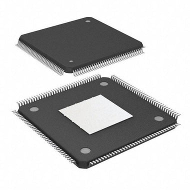
4. Pinout & Package Information
The 10M16SAU169I7G is offered in the UBGA-169 (Ultra-Fine-Pitch BGA) package measuring 11×11 mm with a 0.8 mm ball pitch. The package provides 130 user I/O pins organized across multiple I/O banks, plus dedicated configuration, JTAG, power, and analog input pins.

When designing the PCB footprint, note the following:
- Decoupling capacitors (100 nF ceramic) should be placed as close as possible to every VCC and VCCIO pin.
- The analog supply pins (VCCADC, GNDADC) require a separate filtered power plane for best ADC performance.
- JTAG pins (TCK, TDI, TDO, TMS) should include 10 kΩ pull-up/pull-down resistors as recommended in the MAX 10 Device Handbook.
5. Application Circuit & Design Guide
The MAX 10 10M16 FPGA is widely used in industrial control, motor drive, sensor aggregation, video bridging, and communication protocol conversion. Below is the MAX 10 FPGA Development Kit board, a reference design that demonstrates a complete system built around the MAX 10 device family.

Typical design considerations:
- Power supply – The device requires a 1.2 V core rail and 2.5/3.3 V I/O rails. Use a multi-output PMIC or LDO regulators with proper sequencing (VCCint → VCCIO).
- Clock source – A 50 MHz oscillator connected to a dedicated clock input pin is the standard reference; on-chip PLLs multiply this to the desired internal frequencies.
- Programming – Use the Intel USB-Blaster II for JTAG programming. The internal flash supports In-System Programming (ISP) and remote update via a soft-core processor.
- Quartus Prime Lite – The free Quartus Prime Lite Edition fully supports MAX 10 devices for design entry, synthesis, place-and-route, and timing analysis.
MAX 10 FPGA Tutorial Video
6. Frequently Asked Questions
What is the 10M16SAU169I7G?
The 10M16SAU169I7G is a non-volatile FPGA from the Intel (Altera) MAX 10 family. It integrates 16,000 logic elements, 549 Kb of embedded RAM, a 12-bit ADC, and 4 PLLs in an 11×11 mm UBGA-169 package with an industrial temperature range of −40 °C to +100 °C.
Does the 10M16SAU169I7G require an external configuration memory?
No. MAX 10 FPGAs store their configuration in on-chip flash memory, so no external EPROM or flash device is needed. The device supports dual configuration images for fail-safe remote updates.
What development tools are needed for the 10M16SAU169I7G?
Intel Quartus Prime Lite Edition (free download) supports design entry in Verilog or VHDL, synthesis, place-and-route, and timing analysis for all MAX 10 devices. Programming is performed via the USB-Blaster or USB-Blaster II JTAG cable.
What is the operating temperature range of the 10M16SAU169I7G?
The "I" suffix indicates the industrial temperature grade, supporting an operating range of −40 °C to +100 °C. This makes it suitable for harsh environments such as factory automation, outdoor equipment, and automotive-adjacent applications.
What are common applications for the MAX 10 10M16 FPGA?
Typical applications include industrial motor control, sensor hub / aggregation, LED panel drivers, video format conversion, protocol bridging (SPI/I2C/UART to Ethernet), power supply sequencing, and IoT edge processing where instant-on and a small form factor are essential.
How does the integrated ADC in the 10M16SAU169I7G work?
The MAX 10 FPGA includes a 12-bit successive-approximation-register (SAR) ADC that can sample at up to 1 MSPS. It supports up to 18 analog input channels and features an internal temperature sensor. The ADC is controlled through a dedicated IP core instantiated via Quartus Platform Designer.