
1. Overview of the 10M16SAU169I7G
The 10M16SAU169I7G is a non-volatile FPGA from the Intel (formerly Altera) MAX 10 family. Built on TSMC's 55 nm embedded NOR flash process, it delivers instant-on capability with integrated dual configuration flash, eliminating the need for an external configuration device. With 16,000 logic elements, an integrated 12-bit ADC, and 130 user I/O pins in a compact 169-ball UBGA package, the 10M16SAU169I7G is ideal for industrial control, motor drives, sensor hubs, and communication bridging applications that require both low power and high reliability.
As part of the MAX 10 series, this device supports single-chip solutions by combining FPGA logic, analog-to-digital conversion, and flash memory on a single die. The industrial-grade temperature range (–40 °C to 100 °C) and speed grade 7 designation make it suitable for harsh-environment deployments.
Looking for other Intel FPGA parts? Browse our selection of Intel FPGA components or check out popular related devices like the 10M08SAU169 series and MAX 10 10M50 family.
2. Key Specifications & Parameters
| Parameter | Value |
|---|---|
| Manufacturer | Intel (Altera) |
| Family | MAX 10 (10M16) |
| Part Number | 10M16SAU169I7G |
| Logic Elements (LEs) | 16,000 |
| Logic Array Blocks (LABs) | 1,000 |
| Embedded Memory | 549 Kbit |
| Embedded Multipliers (18x18) | 45 |
| PLLs | Up to 4 |
| User I/O Pins | 130 |
| ADC | 1x 12-bit, up to 1 MSPS |
| Internal Flash (UFM) | 128 Kbit User Flash Memory |
| Configuration Flash | Dual boot with internal flash |
| Package | 169-ball UBGA (11 x 11 mm) |
| Core Voltage | 1.2 V |
| I/O Voltage | 3.3 V (2.85 V - 3.465 V) |
| Process Technology | 55 nm |
| Speed Grade | 7 |
| Operating Temperature | -40 C to +100 C (Industrial) |
| Memory Interface Support | DDR2, DDR3, LPDDR2 |
| ESD Rating (HBM) | >= 2000 V |
| RoHS Compliant | Yes (Pb-free) |
3. Block Diagram & Architecture
The MAX 10 architecture integrates programmable logic, embedded memory blocks, DSP blocks, PLLs, an ADC, and user flash memory into a single monolithic device. The block diagram below illustrates the key functional blocks and their interconnections within the 10M16SAU169I7G.
Key architectural highlights include the Adaptive Logic Module (ALM)-compatible logic elements, M9K embedded memory blocks (each providing 9 Kbit), and hardened 18x18 multiplier DSP blocks capable of efficient signal processing. The integrated 12-bit SAR ADC with up to 17 analog input channels enables direct analog sensor interfacing without external components.
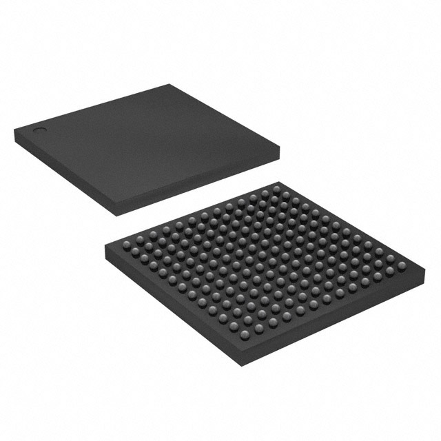
4. Package Information & Pinout
The 10M16SAU169I7G ships in a 169-ball UBGA (Ultra Fine-pitch Ball Grid Array) package measuring 11 x 11 mm with a 0.8 mm ball pitch. This compact surface-mount package is well-suited for space-constrained PCB designs.
With 130 user I/O pins organized across multiple I/O banks, the device supports a variety of I/O standards including LVTTL, LVCMOS, SSTL, HSUL, and differential LVDS. Each I/O bank features independent VCCIO supply, enabling multi-voltage interfacing in a single design. Pin migration is supported across the MAX 10 U169 package family, allowing designers to scale from 10M02 through 10M16 without PCB redesign.
5. Typical Applications & Development
The 10M16SAU169I7G is widely used across industrial, communications, and consumer electronics applications. Its instant-on non-volatile architecture and integrated ADC make it especially attractive for:
- Industrial automation - motor control, PLC I/O expansion, sensor aggregation
- Communications - protocol bridging (SPI/I2C/UART), Ethernet packet processing
- Consumer & IoT - smart sensors, wearable preprocessing, edge inference
- Test & measurement - data acquisition systems, digital oscilloscopes
- Automotive - infotainment system co-processing, display bridging

Intel provides the MAX 10 FPGA Development Kit and the free Quartus Prime Lite Edition toolchain for development, simulation, and programming. The following video provides an introduction to MAX 10 FPGA development:
6. Frequently Asked Questions (FAQ)
- Q1: What is the difference between 10M16SAU169I7G and 10M16SAU169C8G?
- The "I7G" suffix indicates an industrial-grade device (-40 C to +100 C) with speed grade 7, while "C8G" is a commercial-grade device (0 C to +85 C) with speed grade 8. The I7G variant is suitable for harsher environments at a slightly higher cost.
- Q2: Does the 10M16SAU169I7G require an external configuration memory?
- No. MAX 10 FPGAs feature integrated dual configuration flash memory, enabling instant-on operation and remote field updates without an external EPROM or flash device.
- Q3: How many analog input channels does the integrated ADC support?
- The on-chip 12-bit SAR ADC supports up to 17 single-ended analog input channels (shared with I/O pins) at sample rates up to 1 MSPS, suitable for temperature sensing, voltage monitoring, and basic data acquisition.
- Q4: What design software is needed to program the 10M16SAU169I7G?
- Intel's Quartus Prime Lite Edition (free) fully supports all MAX 10 devices. It includes synthesis, place-and-route, timing analysis, and the built-in USB Blaster programmer interface for JTAG configuration.
- Q5: Can I migrate my design from 10M08 to 10M16 within the U169 package?
- Yes. Intel designed the MAX 10 U169 package family for pin-compatible migration across 10M02, 10M04, 10M08, and 10M16 densities, enabling design scalability without PCB changes.
- Q6: What memory interfaces does the 10M16SAU169I7G support?
- The device supports DDR2, DDR3, and LPDDR2 external memory interfaces through its hard memory controller, with data rates up to 300 MHz (DDR3-600). This allows integration of external SDRAM for buffering and processing-intensive applications.


