
Request a Quote · 10M16SAU169I7G
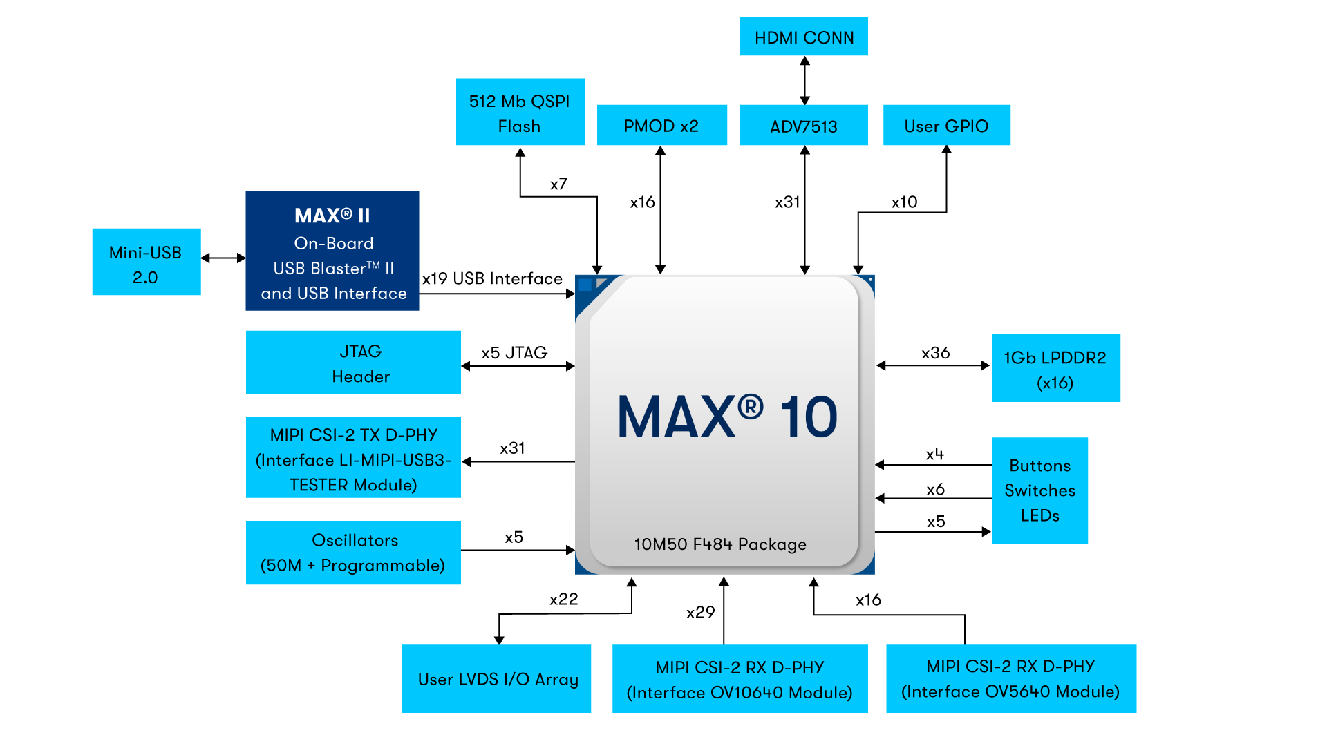
10M16SAU169I7G Functional Block Diagram — MAX 10 FPGA Architecture with Logic Elements, Embedded Memory, ADC Block, and User I/O (Source: Altera/Intel Datasheet)
The 10M16SAU169I7G is a non-volatile, single-chip FPGA from Altera’s (now Intel) MAX 10 family, built on 55 nm flash process technology. It delivers 16,000 logic elements (LEs), 549 Kb of embedded SRAM (M9K blocks), up to 2,304 Kb of user flash memory (UFM), and an integrated dual 12-bit ADC — all within a compact 169-ball UBGA package. With an industrial-grade I7G speed grade operating from −40°C to +100°C, this device enables instant-on functionality with no external configuration memory required, making it an ideal fit for harsh-environment industrial control, sensor aggregation, motor drives, and mission-critical embedded systems.
Table of Contents
1. Overview and Core Features
The MAX 10 FPGA family represents Altera’s most cost-optimized non-volatile FPGA platform. The 10M16SAU169I7G sits in the mid-range of the family, offering 16,000 logic elements — sufficient for moderately complex digital designs including state machines, protocol bridges, and sensor fusion pipelines. Unlike SRAM-based FPGAs that require external flash or EEPROM for configuration, MAX 10 devices store their configuration internally in on-chip flash, enabling instant-on operation within milliseconds of power-up.
Key features of the 10M16SAU169I7G include dual configuration images for remote update with fail-safe fallback, an integrated dual 12-bit successive-approximation ADC with up to 18 analog input channels, and support for single-supply operation. The device provides 4 PLLs and global clock networks supporting frequencies up to 472.5 MHz, enabling complex clocking schemes without external clock management ICs. With 130 maximum user I/O pins available on the U169 package variant, designers gain substantial connectivity for multi-sensor and multi-protocol applications. The industrial temperature rating (−40°C to +100°C) makes this variant particularly suited for factory automation, outdoor installations, and transportation systems.

10M16SAU169I7G Package — MAX 10 FPGA 169-Ball UBGA (11 mm × 11 mm) Component (Source: Altera MAX 10 Product Family)
2. Specifications and Parameter Table
| Parameter | Value |
|---|---|
| Manufacturer | Altera (Intel) |
| Family | MAX 10 FPGA |
| Part Number | 10M16SAU169I7G |
| Logic Elements (LEs) | 16,000 |
| Embedded Memory (M9K SRAM) | 549 Kb |
| User Flash Memory (UFM) | 2,304 Kb |
| Embedded Multipliers (18×18) | 45 |
| PLLs | 4 |
| Maximum User I/O Pins | 130 |
| ADC | Dual 12-bit SAR, up to 1 MSPS, 18 analog channels |
| Core Voltage | 1.2 V |
| I/O Supply Voltage | 2.85 V ~ 3.465 V |
| Speed Grade | I7G (industrial, speed grade 7) |
| Process Technology | 55 nm Flash |
| Package | 169-Ball UBGA (11 mm × 11 mm) |
| Configuration | Internal flash (instant-on), dual boot images |
| Operating Temperature | −40°C to +100°C (Industrial) |
| RoHS Compliance | RoHS3 Compliant |
Looking for 10M16SAU169I7G Inventory?
Check our real-time stock levels, pricing, and volume discounts for global distribution.
Check 10M16SAU169I7G Stock3. Architecture, Pinout, and Application Circuit
The MAX 10 architecture is organized around a sea of adaptive logic modules (ALMs), each containing a 4-input look-up table (LUT), a programmable register, and dedicated carry chain logic. The 10M16SAU169I7G provides 16,000 of these logic elements interconnected through a columnar routing fabric. Embedded M9K SRAM blocks, each 9,216 bits deep, are distributed throughout the array for local storage of FIFOs, filter coefficients, and register files. The user flash memory (UFM) block provides 2,304 Kb of non-volatile storage accessible at runtime for storing calibration data, encryption keys, or application parameters.
The integrated dual 12-bit ADC operates at up to 1 MSPS per channel and supports single-ended analog inputs on up to 18 channels, enabling direct sensor interfacing without external ADC ICs. The ADC includes an internal temperature sensor and voltage reference. For clocking, four PLLs provide frequency synthesis, clock multiplication/division, and phase shifting, supporting input frequencies from 5 MHz to 472.5 MHz. The 169-ball UBGA package maps I/O pins across eight I/O banks, each independently configurable for different voltage standards including LVTTL, LVCMOS, SSTL, HSTL, and LVDS.
A typical application circuit for the 10M16SAU169I7G requires a 1.2 V core supply (VCC), a 2.5 V PLL supply (VCCA), and bank-specific VCCIO supplies. Altera recommends placing 100 nF decoupling capacitors on each VCC and VCCIO pin, with a bulk 10 µF capacitor near each voltage regulator. The JTAG interface (TCK, TDI, TDO, TMS) provides in-system programming and debug access, while the optional configuration pins support dual-image boot with automatic fallback. The industrial temperature rating ensures reliable operation across the full −40°C to +100°C range without derating.
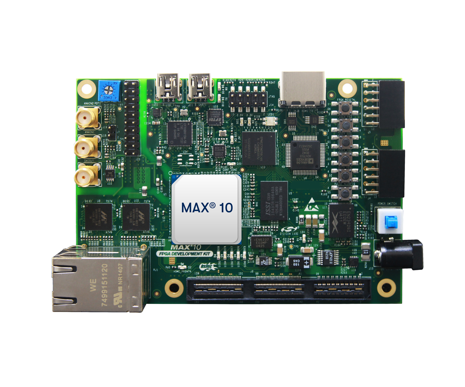
MAX 10 FPGA Development Kit — Evaluation Board Featuring 10M16 FPGA with JTAG, SDRAM, ADC Headers, and Expansion Interfaces (Source: Altera MAX 10 Development Kit)
4. Video: MAX 10 FPGA Design Tutorial
This tutorial walks through the Altera MAX 10 FPGA evaluation kit setup and Quartus Prime design flow. Learn how to create projects targeting MAX 10 devices like the 10M16SAU169I7G, configure pin assignments for the UBGA-169 package, program the internal flash, and leverage the integrated ADC — essential skills for any MAX 10 FPGA design.
5. Equivalents, Cross-Reference, and Lifecycle
The 10M16SAU169I7G carries an Active production status from Altera/Intel with long-term supply commitment. For pin-compatible and functionally similar alternatives within the MAX 10 family, consider:
- 10M16SAU169C8G — Commercial-temperature variant (C8G speed grade) of the same 16K LE device in U169 package. Cost-effective option for designs that do not require extended industrial temperature range.
- 10M08SAE144C8G — A lower-density option with 8,000 logic elements in 144-pin EQFP package. Suitable for cost-down redesigns where the full 16K LE capacity is not needed.
- 10M04SCE144C8G — Entry-level MAX 10 with 4,000 LEs and 144-pin EQFP package. Ideal for simple I/O expansion, LED control, and basic protocol conversion tasks.
When migrating between MAX 10 variants, all devices share the same Quartus Prime Lite toolchain and IP ecosystem, minimizing design porting effort. Verify I/O pin count and bank assignments when changing packages. Check 10M16SAU169I7G Inventory & Pricing at WWDParts for current lead times.
6. Frequently Asked Questions (FAQ)
Q1: What is the 10M16SAU169I7G, and what applications is it designed for?
The 10M16SAU169I7G is a non-volatile FPGA from Altera’s MAX 10 family, integrating 16,000 logic elements, embedded memory, user flash, and a dual 12-bit ADC in a 169-ball UBGA package. With its industrial temperature rating (−40°C to +100°C), it is designed for harsh-environment applications including factory automation, motor control, sensor aggregation, protocol bridging, transportation systems, and outdoor IoT edge gateways.
Q2: Does the 10M16SAU169I7G require an external configuration flash chip?
No. MAX 10 FPGAs store their configuration in internal flash memory, eliminating the need for external EEPROM or SPI flash. The device supports dual configuration images, enabling secure remote firmware updates with automatic fallback to a known-good image if the primary image fails.
Q3: What is the integrated ADC capable of in the 10M16SAU169I7G?
The on-chip dual ADC features 12-bit successive-approximation (SAR) converters running at up to 1 MSPS. It supports up to 18 single-ended analog input channels with an input range of 0 V to the analog reference voltage. It also includes an internal temperature sensor and voltage monitor, making it suitable for direct sensor interfacing in industrial and IoT applications without an external ADC.
Q4: What is the difference between the 10M16SAU169I7G and the 10M16SAU169C8G?
Both devices share the same 16,000 LE architecture and 169-ball UBGA package. The key difference is the operating temperature and speed grade: the I7G variant is industrial-rated (−40°C to +100°C, speed grade 7), while the C8G is commercial-rated with speed grade 8. Choose the I7G for applications exposed to extreme temperatures or requiring military/industrial reliability margins.
Q5: What development tools are needed to design with the 10M16SAU169I7G?
Altera’s Quartus Prime Lite Edition (free) fully supports all MAX 10 devices. The toolchain includes synthesis, place-and-route, timing analysis, and the Platform Designer (formerly Qsys) system integration tool. JTAG-based programming is supported via Intel’s USB-Blaster or USB-Blaster II download cables. The MAX 10 FPGA Development Kit provides a ready-to-use hardware platform for prototyping.
Q6: What are the power supply requirements for the 10M16SAU169I7G?
The device requires a 1.2 V core supply (VCC), a 2.5 V analog PLL supply (VCCA), and I/O bank supplies (VCCIO) configurable from 1.2 V to 3.3 V per bank. A separate 1.2 V supply (VCC_ONE) powers the configuration flash. Altera recommends using low-noise LDO regulators with 100 nF decoupling capacitors on every power pin and 10 µF bulk capacitors at each regulator output.

Alan Carter
Semiconductor Technical Writer · WWDParts.com


