The 10M16SAU169I7G is a non-volatile FPGA from Intel's (formerly Altera) MAX 10 family, fabricated on a 55 nm flash process with a 1.2 V core supply. It integrates 16,000 logic elements, 549 Kbit of embedded M9K SRAM, 46 embedded 18×18 multipliers, 4 PLLs, and an integrated 12-bit ADC in a compact 169-ball UBGA package. With 130 user I/O pins and industrial-grade operation (-40 °C to 100 °C), the 10M16SAU169I7G targets embedded control, industrial IoT, and sensor-interface applications where instant-on configuration, wide temperature tolerance, and integrated analog acquisition are essential.
What Is the 10M16SAU169I7G?
The 10M16SAU169I7G belongs to the MAX 10 family — Intel's single-chip, non-volatile FPGA line introduced in 2014. The part number decodes as follows: "10M16" indicates the 16,000-LE density variant, "SA" designates the feature set with analog capability (dual ADC), "U169" identifies the 169-ball UBGA (Ultra-Fine-Pitch Ball Grid Array) package, "I7" denotes industrial-grade silicon at speed grade 7 (-40 °C to 100 °C), and the trailing "G" signifies RoHS-compliant lead-free terminations.
The MAX 10 architecture fundamentally differs from traditional FPGA families by embedding non-volatile flash memory for configuration storage directly on the die. This eliminates the need for external configuration ROMs, CPLDs, or boot processors — the device powers up instantly from its internal flash in under 10 ms. The 10M16 variant supports dual configuration images in flash, enabling robust remote update with automatic fallback to a known-good golden image if the primary configuration fails.
Internally, the 16,000 logic elements are organized into 1,000 Logic Array Blocks (LABs), each containing 16 adaptive LEs with four-input LUTs, programmable registers, carry chains, and register packing capability. The 60 M9K embedded memory blocks deliver 549 Kbit of configurable SRAM — usable as single-port RAM, dual-port RAM, ROM, FIFO, or shift registers at up to 315 MHz. The 46 embedded 18×18 multipliers support DSP-intensive operations, and four general-purpose PLLs with five output counters each provide flexible clock synthesis across 10 global clock networks.

Pinout Configuration and Packaging
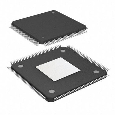
The 10M16SAU169I7G is housed in a 169-ball UBGA (Ultra-Fine-Pitch Ball Grid Array) package with a compact 11×11 mm body and 0.8 mm ball pitch. The UBGA-169 package offers the smallest footprint available for the 10M16 density, making it ideal for space-constrained industrial modules, IoT gateways, and portable instrumentation where board area is at a premium.
Of the 169 balls, 130 are available as general-purpose user I/O pins distributed across 8 independent I/O banks. Each bank supports its own VCCIO supply rail (1.2 V to 3.3 V), enabling mixed-voltage interfacing across different peripherals within a single device. The I/O element (IOE) architecture supports programmable drive strength, slew rate control, on-chip series termination (OCT), and bus-hold functionality. Dedicated clock input pins connect directly to the global clock network and PLLs for low-jitter clock distribution.
The UBGA-169 package provides JTAG configuration pins (TCK, TDI, TDO, TMS) for programming and debug via USB Blaster II. Unlike SRAM-based FPGAs, no external configuration device or MSEL configuration mode pins are required — the MAX 10 boots autonomously from its internal flash memory. Analog input pins for the integrated ADC are multiplexed with specific I/O pins and require external anti-aliasing filtering for precision applications.
Specifications Parameter Table
| Specification | Technical Details |
|---|---|
| Device Family | MAX 10 (Intel / Altera) |
| Process Node | 55 nm flash-based CMOS |
| Logic Elements (LEs) | 16,000 |
| Logic Array Blocks (LABs) | 1,000 |
| M9K Memory Blocks | 60 |
| Total Embedded RAM | 549 Kbit |
| Embedded 18×18 Multipliers | 46 |
| PLLs | 4 (5 output counters per PLL) |
| Global Clock Networks | 10 |
| User I/O Pins | 130 |
| I/O Banks | 8 |
| Analog-to-Digital Converter | Dual 12-bit SAR ADC, up to 1 MSPS, 17 channels |
| User Flash Memory (UFM) | Up to 736 Kbit (for data storage) |
| Configuration Flash Memory (CFM) | Internal, dual-image support |
| Package | 169-ball UBGA (11×11 mm, 0.8 mm pitch) |
| Core Voltage (VCCINT) | 1.14 V to 1.26 V (nominal 1.2 V) |
| Max I/O Voltage (VCCIO) | 3.6 V |
| Speed Grade | I7 (Industrial, -40 °C to 100 °C) |
| I/O Standards | LVTTL, LVCMOS, SSTL-2, SSTL-18, SSTL-15, HSTL, LVDS, PCI |
| External Memory Interfaces | DDR3, DDR2, DDR, SDR SDRAM |
| Configuration | Internal flash (instant-on), JTAG |
| RoHS Compliant | Yes (lead-free, "G" suffix) |
Typical Applications and Circuit Considerations
The 10M16SAU169I7G is designed for industrial and embedded applications that demand non-volatile instant-on operation, wide-temperature reliability, and integrated analog acquisition. Its combination of 16,000 LEs, embedded ADC, flash configuration, and industrial-grade rating makes it suitable for demanding deployment environments:
- Industrial IoT and Sensor Fusion: The integrated dual 12-bit ADC eliminates external ADC ICs for monitoring temperature, pressure, current, and voltage sensors. Combined with the FPGA logic, custom sensor-processing pipelines can perform real-time filtering, threshold detection, and protocol conversion to Modbus, CAN, or Ethernet — all in a single chip.
- Motor Control and Power Electronics: The 46 embedded multipliers accelerate PID loop calculations, space-vector PWM generation, and encoder signal processing for multi-axis servo and stepper motor drives. The -40 °C to 100 °C operating range supports deployment in factory-floor environments without additional thermal management.
- Remote Equipment and Edge Computing: The dual-boot flash configuration with automatic fallback enables secure over-the-air FPGA updates in remote installations — cell towers, pipeline monitors, weather stations — where physical access for reprogramming is impractical. The instant-on capability ensures the system recovers from power cycles without a boot processor.
- Communications and Protocol Bridging: With 130 I/O pins supporting diverse voltage standards, the 10M16SAU169I7G serves as a high-speed protocol bridge between legacy and modern interfaces — LVDS-to-CMOS conversion, multi-channel UART aggregation, or custom serial-to-parallel engines for optical networking equipment.
- Test and Measurement Instrumentation: The integrated ADC combined with DSP-capable logic enables compact data acquisition systems, pattern generators, and protocol analyzers. User Flash Memory (UFM) provides on-chip non-volatile storage for calibration data, device serial numbers, and test configurations.
For power supply design, Intel recommends a three-rail power architecture: 1.2 V core (VCCINT), 2.5 V PLL analog (VCCA), and per-bank I/O (VCCIO at 1.2–3.3 V). Each VCC pin requires a 0.1 µF ceramic bypass capacitor placed within 2 mm of the ball, supplemented by 10–47 µF bulk capacitors per rail. The BGA thermal pad requires adequate via stitching to the ground plane. Browse MAX 10 Series components for related power management and companion ICs.

Video Tutorial
Equivalents, Cross-Reference, and Lifecycle
The 10M16SAU169I7G remains in active production as of 2026, with the MAX 10 family positioned as Intel's recommended non-volatile FPGA platform for cost-optimized embedded designs. For designs requiring pin-compatible or functionally equivalent alternatives, consider these options:
- 10M16SAU169C8G: Identical device in commercial-grade (0 °C to 85 °C) with speed grade 8. Pin-to-pin compatible — use for benign operating environments where the wider industrial temperature range is unnecessary.
- 10M08SAU169C8G: Same UBGA-169 package with reduced resources (8,000 LEs, 378 Kbit RAM, 24 multipliers). Pin-compatible cost-down option when logic utilization permits.
- 10M16SAE144C8G: Same 10M16 logic density in a larger 144-EQFP package (20×20 mm) with 101 user I/Os. Easier for prototyping and hand-soldering due to the leaded package format.
- Lattice MachXO3LF-6900: A competing non-volatile FPGA with 6,900 LUTs and instant-on capability, though with fewer logic resources and no integrated ADC. Consider for designs requiring a second-source strategy.
When sourcing the 10M16SAU169I7G, verify the full ordering code — the "I7" suffix confirms industrial temperature and speed grade 7; the "SA" prefix confirms the analog-enabled feature set with dual ADC. Variants without the "A" (e.g., 10M16SCU169I7G) lack the ADC blocks. Check 10M16SAU169I7G Inventory & Pricing for current stock and lead times. Also explore our catalog of Intel FPGA and programmable logic devices for cross-compatible alternatives.
Frequently Asked Questions (10M16SAU169I7G FAQ)
Q: What is the difference between 10M16SAU169I7G and 10M16SAU169C8G?
A: Both are MAX 10 10M16 FPGAs in the same UBGA-169 package with identical logic resources (16,000 LEs, 549 Kbit RAM, 4 PLLs). The key difference is operating range: the 10M16SAU169I7G is an industrial-grade device rated for -40 °C to 100 °C at speed grade 7, while the 10M16SAU169C8G is commercial-grade (0 °C to 85 °C) at speed grade 8. The I7G variant is required for applications exposed to extreme temperatures such as outdoor industrial equipment and automotive peripherals.
Q: What development tools are needed to program the 10M16SAU169I7G?
A: The 10M16SAU169I7G is programmed using Intel Quartus Prime Lite Edition, which is free with no license restrictions for MAX 10 devices. Design entry supports Verilog, VHDL, and schematic capture. A USB Blaster II JTAG programmer is required for configuration and debugging. The device features internal flash-based configuration storage, eliminating the need for an external configuration ROM. ModelSim-Intel FPGA Edition is available for functional and timing simulation.
Q: Does the 10M16SAU169I7G have an analog-to-digital converter?
A: Yes. The MAX 10 "SA" variants integrate dual ADC blocks, each featuring a 12-bit SAR ADC with up to 17 analog input channels and a maximum sampling rate of 1 MSPS. The ADC can be used for on-die temperature sensing, external voltage monitoring, and general-purpose analog signal acquisition — eliminating the need for an external ADC IC in many sensor and monitoring applications.
Q: What I/O voltage standards does the 10M16SAU169I7G support?
A: The 10M16SAU169I7G supports a comprehensive range of I/O standards including 3.3 V / 2.5 V / 1.8 V / 1.5 V / 1.2 V LVCMOS, 3.0 V / 3.3 V LVTTL, SSTL-2, SSTL-18, SSTL-15 for DDR3 SDRAM interfaces, and HSTL for high-speed memory. Differential standards include LVDS, mini-LVDS, RSDS, and LVPECL. The 8 independent I/O banks each accept their own VCCIO supply, enabling mixed-voltage designs within a single device.
Q: Can the 10M16SAU169I7G boot without an external configuration device?
A: Yes. The MAX 10 family stores its configuration in on-chip flash memory, enabling instant-on operation without any external configuration ROM, CPLD, or boot processor. The device powers up and begins operating within milliseconds of power-on. Dual-boot capability allows storing two configuration images in the internal flash, providing automatic fallback to a golden image if the primary configuration is corrupted during a remote field update.
Q: What is the power consumption of the 10M16SAU169I7G?
A: Static (quiescent) power consumption is typically 90–120 mW depending on junction temperature and voltage conditions. Dynamic power varies with design complexity, clock frequency, logic utilization, and I/O switching activity. Intel provides the PowerPlay Early Power Estimator (EPE) spreadsheet for pre-design budgeting and the Quartus Prime Power Analyzer for post-compilation accuracy. The 55 nm process and 1.2 V core supply keep total power manageable for thermally constrained industrial enclosures operating at the full -40 °C to 100 °C range.

Alan Carter
Senior Hardware Engineer & Component Specialist
Alan has over 15 years of expertise in embedded systems design, FPGA architecture, and global semiconductor supply chains. He specializes in component cross-referencing, lifecycle management, and helping OEMs navigate supply shortages.