Request a Quote · 10M16SAU169I7G

10M16SAU169I7G Functional Block Diagram — Intel MAX 10 FPGA with integrated flash, ADC, and DSP blocks (Source: Intel/Altera MAX 10 Device Overview)
The 10M16SAU169I7G is an Intel (formerly Altera) MAX 10 family FPGA featuring 16,000 logic elements, integrated 12-bit analog-to-digital converter, and on-die flash memory for instant-on configuration in under 10 ms. Built on 55nm technology and housed in a compact 169-ball UBGA package, this single-supply FPGA operates from 2.85 V to 3.465 V across the full industrial temperature range of −40°C to +100°C. With 562 Kbit of embedded SRAM, 45 embedded multipliers, 4 PLLs, and 130 user I/O pins, the 10M16SAU169I7G delivers a compelling combination of performance, integration, and low power consumption for cost-sensitive embedded applications in industrial automation, communications infrastructure, and consumer electronics.
Table of Contents
1. Overview and Core Features
The Intel MAX 10 family represents a breakthrough in non-volatile FPGA technology, integrating configuration flash memory, user flash memory (UFM), and an analog-to-digital converter alongside traditional FPGA logic fabric—all within a single device. The 10M16SAU169I7G occupies the mid-range of the MAX 10 lineup, providing 16,000 logic elements organized into 1,000 logic array blocks (LABs), each containing 16 adaptive logic modules (LEs) with four-input look-up tables and programmable registers.
Key differentiators of the 10M16SAU169I7G include its instant-on capability—on-die flash memory eliminates the need for external configuration devices, enabling the FPGA to configure and begin operation in under 10 ms after power-up. The integrated dual-image configuration flash supports fail-safe remote updates, while the user flash memory block provides non-volatile storage for application data, calibration coefficients, or encryption keys without requiring external EEPROM or SPI flash. The single-supply 3.3 V operation and 169-UBGA package (11 mm × 11 mm) minimize both board complexity and PCB footprint.

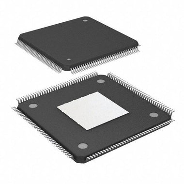
10M16SAU169I7G 169-UBGA Package — 11 mm × 11 mm BGA with 0.8 mm ball pitch (Source: MicrochipUSA)
2. Specifications and Parameter Table
| Parameter | Value |
|---|---|
| Manufacturer | Intel (formerly Altera) |
| Family | MAX 10 (10M16) |
| Device Type | Non-Volatile FPGA |
| Logic Elements (LEs) | 16,000 |
| Logic Array Blocks (LABs) | 1,000 |
| Embedded Memory (M9K) | 562,176 bits (549 Kbit) |
| Embedded Multipliers (18×18) | 45 |
| PLLs | 4 |
| Global Clock Networks | 20 |
| ADC | 12-bit, up to 25 MSPS (dual ADC blocks) |
| User I/O Pins | 130 |
| Flash Memory | Integrated CFM + UFM (instant-on, dual-image) |
| Memory Interfaces | DDR2 / DDR3 / LPDDR2 (via soft controller) |
| Core Voltage | 1.2 V (internal) |
| Supply Voltage (Single-Supply) | 2.85 V to 3.465 V (3.3 V nominal) |
| Operating Temperature | −40°C to +100°C (TJ, Industrial) |
| Speed Grade | 7 (Industrial) |
| Technology Node | 55 nm |
| Package | 169-UBGA (11 mm × 11 mm, 0.8 mm pitch) |
| Packaging | Tray |
| RoHS Compliance | RoHS Compliant, Pb-Free |
Looking for 10M16SAU169I7G Inventory?
Check our real-time stock levels, pricing, and volume discounts for worldwide distribution.
Check 10M16SAU169I7G Stock3. Architecture, Pinout, and Application Circuit
The MAX 10 FPGA architecture centers on a regular array of logic array blocks (LABs), each containing 16 logic elements. Each LE provides a four-input look-up table (LUT), a programmable register, and carry chain logic for efficient arithmetic operations. The embedded memory system consists of M9K blocks—each providing 9,216 bits (including parity)—that can be configured as RAM, ROM, shift registers, or FIFO buffers in various width and depth combinations.
The 45 embedded 18×18 multiplier blocks support one 18-bit or two 9-bit multiplication operations per block, delivering substantial DSP throughput for digital filtering, FFT, and signal processing algorithms. Four phase-locked loops (PLLs) provide clock synthesis, multiplication, division, and phase shifting with up to 20 global clock distribution networks ensuring low-skew clock delivery across the device.
The integrated 12-bit ADC supports up to 18 single-ended analog inputs with a cumulative sampling rate of 25 MSPS, plus an on-chip temperature sensor for thermal management. For the typical application circuit, designers should connect the 3.3 V supply to VCCIO and VCC pins with 0.1 µF and 10 µF decoupling capacitors, configure JTAG pins for programming via USB-Blaster, and route the analog reference voltage (VREFP) with proper filtering for ADC accuracy.
%3C%2Ftext%3E%3Cline%20x1%3D%22520%22%20y1%3D%22200%22%20x2%3D%22600%22%20y2%3D%22210%22%20stroke%3D%22%236a1b9a%22%20stroke-width%3D%222%22%3E%3C%2Fline%3E%3Crect%20x%3D%22600%22%20y%3D%22260%22%20width%3D%22140%22%20height%3D%2240%22%20fill%3D%22%23e0f7fa%22%20stroke%3D%22%2300695c%22%20rx%3D%224%22%3E%3C%2Frect%3E%3Ctext%20x%3D%22670%22%20y%3D%22285%22%20text-anchor%3D%22middle%22%20font-family%3D%22Arial%2Csans-serif%22%20font-size%3D%2211%22%20fill%3D%22%2300695c%22%3EAnalog%20Inputs%20(ADC)%3C%2Ftext%3E%3Cline%20x1%3D%22520%22%20y1%3D%22250%22%20x2%3D%22600%22%20y2%3D%22280%22%20stroke%3D%22%2300695c%22%20stroke-width%3D%222%22%3E%3C%2Fline%3E%3Ctext%20x%3D%22400%22%20y%3D%22380%22%20text-anchor%3D%22middle%22%20font-family%3D%22Arial%2Csans-serif%22%20font-size%3D%2213%22%20fill%3D%22%23607d8b%22%3ETypical%20Application%20Circuit%20%E2%80%94%20Single-Supply%203.3V%20Configuration%3C%2Ftext%3E%3C%2Fsvg%3E)
10M16SAU169I7G Typical Application Circuit — Single-Supply 3.3V Design with DDR3, JTAG, and ADC Interface (Source: Intel MAX 10 Device Handbook)
4. Video: MAX 10 FPGA Development Tutorial
This tutorial demonstrates how to set up and program the Intel MAX 10 FPGA Evaluation Kit using Quartus Prime. The video covers device configuration, pin assignment, JTAG programming via USB-Blaster, and a basic LED blink design—all directly applicable to designs using the 10M16SAU169I7G in the 169-UBGA package.
5. Equivalents, Cross-Reference, and Lifecycle
The 10M16SAU169I7G carries an Active production status from Intel/Altera with ongoing supply through major distributors. The “I7G” suffix denotes industrial temperature grade (−40°C to +100°C) with speed grade 7 in lead-free (green) packaging. For designs requiring different specifications or alternative sources, engineers should consider:
- 10M16SAU169C8G — The commercial temperature variant (−40°C to +85°C) with speed grade 8 in the same 169-UBGA package. Suitable for non-industrial applications where extended temperature range is not required.
- 10M16SCU169I7G — The single-supply compact variant with reduced I/O capability but identical logic capacity, optimized for ultra-low-power applications.
- 10M25SAE144C8G — A higher-capacity MAX 10 device with 25,000 logic elements in a 144-EQFP package, for designs needing more logic resources while staying within the MAX 10 ecosystem.
- 10M08SAE144C8G — A lower-cost MAX 10 device with 8,000 logic elements in a 144-EQFP package, ideal for simpler applications that can trade logic capacity for reduced BOM cost.
- EP4CE10E22C8N — An Altera Cyclone IV FPGA with 10,320 logic elements. A cost-effective alternative when on-die flash and ADC are not required, though it needs an external configuration device.
When selecting an alternative, verify that the I/O voltage levels, memory interface requirements, and ADC specifications meet your application needs. Check 10M16SAU169I7G Inventory & Pricing at WWDParts for current lead times and stock availability.
6. Frequently Asked Questions (FAQ)
Q1: What is the 10M16SAU169I7G, and what applications is it designed for?
The 10M16SAU169I7G is a non-volatile FPGA from Intel’s MAX 10 family, featuring 16,000 logic elements, an integrated 12-bit ADC, and on-die flash memory in a 169-UBGA package. It is designed for industrial automation, motor control, sensor aggregation, communications protocol bridging, embedded display interfaces, and consumer electronics requiring instant-on operation, small form factor, and single-supply simplicity. Its industrial temperature rating (−40°C to +100°C) makes it suitable for harsh-environment deployments.
Q2: How does the instant-on flash configuration work on the MAX 10?
The MAX 10 FPGA stores its configuration bitstream in integrated on-die flash memory, eliminating the need for an external configuration PROM or SPI flash. Upon power-up, the device automatically loads the configuration from internal flash and becomes operational in under 10 ms. The dual-image configuration flash (CFM) supports two bitstream images, enabling fail-safe remote field updates—if the primary image is corrupted during an update, the device falls back to the secondary image. Programming is performed via JTAG using the Intel Quartus Prime software and a USB-Blaster cable.
Q3: What external components are needed for a minimal 10M16SAU169I7G design?
A minimal design requires: (1) a 3.3 V regulated power supply with 0.1 µF and 10 µF decoupling capacitors on each VCCIO and VCC pin pair, (2) a 10-pin JTAG header connected to TDI, TDO, TMS, TCK, and TRST pins for programming, (3) pull-up resistors on nCONFIG and nSTATUS pins, and (4) a reference clock oscillator if the PLLs are used. For ADC operation, a clean analog reference voltage (VREFP) with appropriate filtering is needed. No external configuration device is required thanks to the on-die flash.
Q4: Can the 10M16SAU169I7G interface with DDR3 memory?
Yes. The MAX 10 FPGA supports DDR3, DDR3L, DDR2, and LPDDR2 memory interfaces through Intel’s External Memory Interface (EMIF) soft IP core, available in the Quartus Prime software. The 10M16 in the U169 package provides sufficient I/O pins to support a 16-bit DDR3 interface running at up to 300 MHz (600 Mbps per pin). Designers should follow Intel’s board layout guidelines for DDR3 trace matching, impedance control, and power supply decoupling to ensure reliable operation at these data rates.
Q5: What is the difference between the 10M16SAU169I7G and 10M16SAU169C8G?
Both devices contain identical logic resources (16,000 LEs, 549 Kbit M9K RAM, 45 multipliers, 4 PLLs, 130 I/Os) in the same 169-UBGA package. The key differences are: the I7G variant is rated for industrial temperatures (−40°C to +100°C junction) at speed grade 7, while the C8G is rated for commercial temperatures (0°C to +85°C) at speed grade 8. Speed grade 8 offers slightly faster timing but is limited to commercial temperature conditions. Choose the I7G for automotive, industrial, or outdoor applications requiring extended temperature operation.
Q6: How do I use the integrated ADC on the 10M16SAU169I7G?
The integrated 12-bit ADC is accessed through the Altera Modular ADC IP core instantiated in your Quartus Prime design. The ADC supports up to 18 single-ended analog input channels with a cumulative sampling rate of 25 MSPS and includes a built-in temperature sensing diode. Configure the ADC via the Platform Designer (Qsys) tool by selecting the desired channels, sampling sequence, and clock divider. The ADC output data is accessible through an Avalon Memory-Mapped (Avalon-MM) slave interface, making it easy to integrate with NIOS II soft processors or custom state machines. Ensure the analog reference voltage (VREFP) is properly filtered and decoupled for accurate conversions.
For more Intel FPGA options, browse our MAX 10 FPGA catalog or explore our full semiconductor inventory. See also our guide on the latest FPGA technology trends.
Alan Carter, Senior Hardware Engineer
Alan has over 15 years of experience in embedded systems design, specializing in FPGA architecture, digital signal processing, and global semiconductor supply chain management. He frequently contributes technical teardowns and component comparisons.